Agrement ETA 23-0707 pentru ancora surub R-HLX RAWLPLUG R-HLX-HF-ZF, R-HLX-CS-ZF
Tip documentatie: Certificare produs
Salvează pdf
Full screen
Member of
www.eota.eu
Technical and Test Institute
for Construction Prague
Prosecká 811/76a
190 00 Prague
Czech Republic
eota@tzus.cz
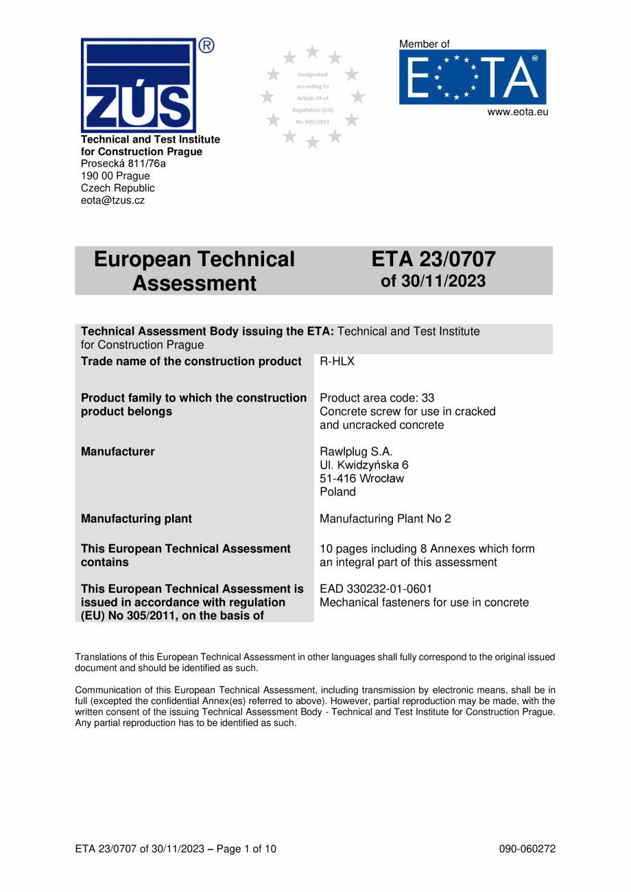
European Technical
Assessment
ETA 23/0707
of 30/11/2023
Technical Assessment Body issuing the ETA: Technical and Test Institute
for Construction Prague
Trade name of the construction product
R-HLX
Product family to which the construction
product belongs
Product area code: 33
Concrete screw for use in cracked
and uncracked concrete
Manufacturer
Rawlplug S.A.
Ul. Kwidzyńska 6
51-416 Wrocław
Poland
Manufacturing plant
Manufacturing Plant No 2
This European Technical Assessment
contains
10 pages including 8 Annexes which form
an integral part of this assessment
This European Technical Assessment is
issued in accordance with regulation
(EU) No 305/2011, on the basis of
EAD 330232-01-0601
Mechanical fasteners for use in concrete
Translations of this European Technical Assessment in other languages shall fully correspond to the original issued
document and should be identified as such.
Communication of this European Technical Assessment, including transmission by electronic means, shall be in
full (excepted the confidential Annex(es) referred to above). However, partial reproduction may be made, with the
written consent of the issuing Technical Assessment Body - Technical and Test Institute for Construction Prague.
Any partial reproduction has to be identified as such.
ETA 23/0707 of 30/11/2023 – Page 1 of 10
090-060272
1.
Technical description of the product
The R-HLX concrete screw in sizes of 10, 12 and 14 is made of carbon steel with
coating.
The anchor is screwed into a drilled cylindrical hole. The special thread of the anchor
cuts an internal thread into the member while setting. The anchorage is characterised
by mechanical interlock in the special thread.
The installed anchor is shown in Annex A1.
2.
Specification of the intended use in accordance with the applicable EAD
The performances given in Section 3 a
re only valid if the anchor is used in compliance
with the specifications and conditions given in Annex B.
The provisions made in this European Technical Assessment are based on an
assumed working life of the anchor of 50 years. The indications given on the working
life cannot be interpreted as a guarantee given by the producer, but are to be regarded
only as a means for choosing the products in relation to the expected economically
reasonable working life of the works.
3.
Performance of the product and references to the methods used for its
assessment
3.1
Mechanical resistance and stability (BWR 1)
Essential characteristic
Characteristic resistance (static and quasi-static loading)
Displacement
3.2
4.
Safety in case of fire (BWR 2)
Essential characteristic
Reaction to fire
Resistance to fire
Performance
See Annex C 1 and C 2
Performance
Class A1 according to EN 13501-1
No performance assessed
Assessment and verification of constancy of performance (AVCP
) system
applied with reference to its legal base
According to the Decision 96/582/EC of the European Commission1, the system 1 of
assessment verification of constancy of performance (see Annex V to the Regulation
(EU) No 305/2011) apply.
5.
Technical details necessary for the implementation of the AVCP system, as
provided in the applicable EAD
Technical details necessary for the implementation of the AVCP system are laid down
in the control plan deposited at Technical and Test Institute for Construction Prague.
Issued in Prague on 30.11.2023
By
Ing. Jiří Studnička, Ph.D.
Head of the Technical Assessment Body
1
Official Journal of the European Communities L 254 08.10.1996
ETA 23/0707 of 30/11/2023 – Page 2 of 10
R-HLX-HF - Installed screw
R-HLX-CS - Installed screw
R-HLX
Product description
Installed conditions
ETA 23/0707 of 30/11/2023 – Page 3 of 10
Annex A 1
Table A1 - Materials
Material
Carbon steel; rupture elongation A5 ≥ 12%
Galvanized zinc plating (≥ 5
μm), acc ISO 4042 or
Zinc flake (≥ 5 μm), acc. ISO 10683
R-HLX – Types
Type
Design
R-HLX-HF
R-HLX-CS
HLX-SI
R-HLX and HLX-SI – Marking
Marking:
R-HLX Identifying mark of the producer
D x L, where:
D – screw size [mm], e. g. 10
L – length of a screw [mm], e. g. 100
HLX-SI-12x100-ZF head
R-HLX
Product description
Materials
Marking
ETA 23/0707 of 30/11/2023 – Page 4 of 10
Annex A 2
Table A2 - Dimensions
Nominal diameter
Threaded outer diameter
Core diameter
Shaft diameter
Head sizes R-HLX-HF
Head sizes CS
dnom
dth
dk
ds
Sw
T
[mm]
[mm]
[mm]
[mm]
[-]
[-]
10
12,7
9,3
9,8
SW15
T50
12
14,9
11,5
11,95
SW17
T50
14
16,9
13,3
13,85
SW21
T50
R-HLX
Product description
Dimensions
ETA 23/0707 of 30/11/2023 – Page 5 of 10
Annex A 2
Specifications of intended use
Anchorages subject to:
• Static and quasi-static loads.
Base materials
• Cracked or uncracked concrete.
• Reinforced or unreinforced normal weight concrete of strength class C20/25 at minimum and
C50/60 a
t maximum according EN 206:2013+A1:2016.
Use conditions (Environmental conditions)
• Structures subject to dry internal conditions.
Design:
• The anchorages are designed under the responsibility of an engineer experienced in anchorages
and concrete work.
• The anchorages are designed in accordance with the EN 1992-4:2018 and Technical Report TR
055, Edition February 2018.
• Verifiable calculation notes and drawings are prepared taking account of the loads to be anchored.
The position of the anchor is indicated on the design drawings (e.g. positions of the fastener relative
to reinforcement or to support, etc.).
Installation:
• Anchor installation carried out by appropriately qualified personnel and under the supervision of the
person responsible for technical matters of the site.
• Use of the anchor only as supplied by the manufacturer without exchanging any components of the
anchor.
• Anchor installation in accordance with the manufacturer’s specifications and drawings
using the
appropriate tools.
• Effective anchoring depth, edge distance and spacing not less than the specified values without
minus tolerance.
• In case of aborted drill hole: new drilling at a minimum distance away of twice the depth of the aborted
hole or smaller distance if the aborted drill hole is filled with high strength mortar and if under shear
or oblique tension load it is not in the direction of load application.
R-HLX
Intended use
Specifications
ETA 23/0707 of 30/11/2023 – Page 6 of 10
Annex B 1
Table B1 - Installation parameters for standard embedment depth
Drill hole Maximum Nominal Min. hole Max. hole Maximum
Minimum Minimum Minimum
diameter cutting embedment depth diameter in installation thickness of spacing
edge
diameter
depth
fixture
torque
concrete
distance
Type
member
d0
dcut,max
hnom
df
Timp,max
hmin
smin
cmin
h0 [mm]
[mm]
[mm]
[mm]
[mm]
[Nm]
[mm]
[mm]
[mm]
R-HLX 10
10
10,45
85
95
14
1000
130
60
60
R-HLX 12
12
12,45
100
110
16
1000
155
80
80
R-HLX 14
1
4
14,45
115
125
18
1000
190
100
100
Table B2 - Installation parameters for medium embedment depth
Drill hole Maximum Nominal Min. hole Max. hole Maximum
Minimum Minimum Minimum
diameter cutting embedment depth diameter in installation thickness of spacing
edge
diameter
depth
fixture
torque
concrete
distance
Type
member
d0
dcut,max
hnom
df
Timp,max
hmin
smin
cmin
h0 [mm]
[mm]
[mm]
[mm]
[mm]
[Nm]
[mm]
[mm]
[mm]
R-HLX 10
10
10,45
75
85
14
1000
120
60
60
R-HLX 12
12
12,45
80
90
16
1000
130
80
80
R-HLX 14
14
14,45
85
95
18
1000
130
100
100
Table B3 – Installation parameters for reduced embedment depth
Drill hole Maximum Nominal Min. hole Max. hole Maximum
Minimum Minimum Minimum
diameter cutting embedment depth diameter in installation thickness of spacing
edge
diameter
depth
fixture
torque
concrete
distance
Type
member
d0
dcut,max
hnom
df
Timp,max
hmin
smin
cmin
h0 [mm]
[mm]
[mm]
[mm]
[mm]
[Nm]
[mm]
[mm]
[mm]
R-HLX 10
10
10,45
55
65
14
1000
100
60
60
R-HLX 12
12
12,45
60
70
16
1000
110
80
80
R-HLX 14
14
14,45
65
75
18
1000
110
100
100
R-HLX
Intended use
Installation parameters
ETA 23/0707 of 30/11/2023 – Page 7 of 10
Annex B 2
Installation instructions
1a
1. Drill the hole with a hammer drill (1a) or a dust-free drill (1b)
to the required depth according to the table.
1b
2.
2. Clean the hole (blow dust at least 4 times with the hand
pump). When using a dust-free drill bit (1b), it is not
necessary to clean the hole.
3.
3. Screw the concrete screw into the hole with an impact
wrench and a suitable impact socket. Tighten until the fixture
is clamped to the substrate.
Installation with any tangential impact wrench.
4.
4. Finish screwing when the screw head is in full contact with
the fastened element/substrate. The screw head must not
be damaged.
R-HLX
Intended use
Installation instructions
ETA 23/0707 of 30/11/2023 – Page 8 of 10
Annex B 3
Table C1 – Characteristic resistance under tension load
Size
Nominal embedment depth
hnom [mm]
Steel failu
re
NRk,s
Characteristic resistance
γMs
Partial safety factor
Pull-out failure
Characteristic resistance
NRk,p,ucr
in uncracked concrete C20/25
Characteristic resistance
NRk,p,cr
in cracked concrete C20/25
C25/30
C30/37
C35/45
Increasing factor
ψc
for concrete
C40/50
C45/55
C50/60
Concrete cone and splitting failure
hef
Effective embedment depth
Factor for concrete cone failure
kucr,N
for uncracked concrete
Factor for concrete cone failure
kcr,N
for cracked concrete
γinst
Robustness
concrete cone failure scr,N
Spacing
scr,sp
splitting failure
concrete cone failure ccr,N
Edge
distance splitting failure
ccr,sp
1)
limited to
N0
55
[kN]
[-]
10
75
85
60
54,3
12
80
100
65
83,1
1,5
14
85
115
111,1
[kN] 13,4 1) 22,3 1) 27,6 1) 15,4 1) 24,6 1) 35,2 1) 16,9 1) 26,4 1) 43,4 1)
[kN]
9,4 1) 15,6 1) 19,3 1) 10,7 1) 17,2 1) 24,6 1) 11,8 1) 18,5 1) 30,4 1)
[-]
1,10
1,22
1,34
1,41
1,48
1,55
[mm]
42
59
68
46
63
[-]
11,0
[-]
7,7
[-]
[mm]
[mm]
[mm]
[mm]
80
49
66
92
1,2
... ascunde
Alte documentatii ale aceleasi game Vezi toate
Fisa tehnica
3 p | RO
R-TFIX-8M
Certificare produs
13 p | RO
R-TFIX-8M