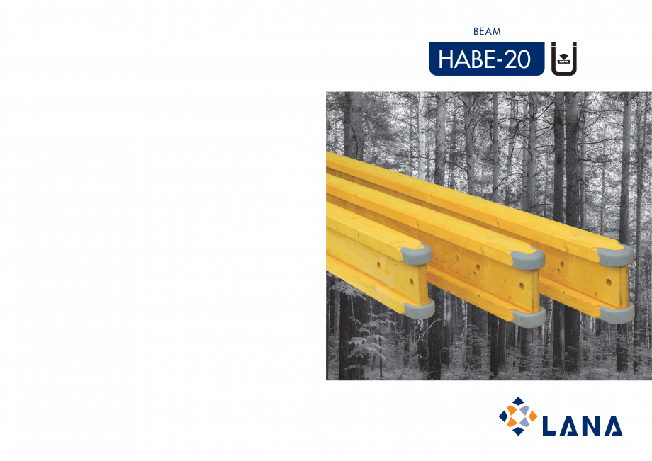
Catalog grinzi de cofrare Lana WELDE H20
BEAM
www.lana.eu
PRODUCTION PLANTS
HABE-20
LANA, S. Coop.
Bº Santxolopetegi, 24 • Apdo. 25
20560 OÑATI (Gipuzkoa)
SPAIN
Tel.: +34 943 780 700
Fax: +34 943 780 790
PEFC/14-35-00131
ER-0585/2000
Czech LANA s.r.o.
Chrudimská 584
582 63 Ždírec nad Doubravou
CZECH REPUBLIC
Tel. +420 569 430 060
Fax. +420 569 430 061
PEFC/08-35-0022
DISTRIBUTOR
DIMENSIONS AND TOLERANCES
TECHNICAL SPECIFICATIONS
HABE 20
Tolerances
Beam height (mm)
200
(+/- 2 mm)
Head height (mm)
40
Head width (mm)
Dimensions
1
Web thickness (mm)
HABE 20
2
Permissible modulus (kNm)
5
(-1,5 %)
Permissible shearing force Q (kN)
11
80
(-1,5 %)
Section modulus1 W x (cm3)
26,8
(+/- 0,5 mm)
Geometrical moment of inertia J x (cm 4)
1. These values apply at a wood moisture content of 12%.
BEAM
apply to new or used concrete formwork beams. An analogously increased
HABE-20
HEADS
Fir wood of the highest quality,
calibrated with levelled edges and
with finger type joints along their
length.
WE
BS
Of a three-layer board with a
thickness of 27 mm.
ANTI-HUMIDITY TREATMENT
Protective paintwork throughout the
beam.
CERTIFICATIONS
ÜZ-BWU03-l 14.24.29
certificate by MPA Sttutgart
in accordance with european
regulation EN 13377 and DIN V
20000-2.
Gluing licence C1 according with
DIN 1052-10 certified bu MPA
Sttutgart.
factor of safety needs to be added for severely worn beams.
Distance between
crossbeams
2
200
Admissible Bending
Moment: M=5.0 kNm
40
Admissible Transversal
Strenght: Q=11.0 kN
80
STANDARD SIZES
Slab
thickness
Applications
Advantages
1
Formwork systems
STRENGTH AND SAFETY
Dimensional stability and recovery
capacity after application of load.
High load capacity throughout their
length. Protection against humidity,
knocks and splintering.
Flat main beam
4
Walls
Distance between
main beams
ECONOMICAL
Can be used many times. Good
ratio between price and uses. Easy
storage.
Distance between
supports
3
Civil Works
Max. Deflection of the beam: L/500
Li
ve load: 1,5 kN/m2 or 20% of the concrete weigth
Permissible corrying force of the supports: A = Min. 22 kN
LIGHTNESS
Easy handling and quick assembly.
Minimum weight.
ADAPTABILITY
TO
BUILDING
WORK
Ideal for use with three-layer board.
The beam can be cut at any point.
Supports can be placed between
beams at any point. Can be used in
any kind of formwork.
40
PROTECTED BEAM END
Anti-shock polymer caps specifically
designed to last longer on site.
JOINT
Notched, finger-type joint between
core and wings, throughout their
length.
High-frequency,
highstrength gluing.
4613
1. The values of the section modulus and the geometrical moment of inertia
2. Pursuant to approval notice ÜZ-BWU034 14.24.29
BEAM
Wooden beam for formwork,
consisting of an upper and lower
wing and featuring a central section
consisting of three layers. The union
is designed as a notched and glued
joint.
461
1
SLAB
TOTAL
THICKNESS LOAD
cm
KN/M2
CROSS BEAMS
distance between crossbeams (m)
0,5
0,625
0,75
Te
chnical specification, security workload
Permitted bending moment: Q = 11 kN
Remitted shear force: M = 5 kNm
MAIN BEAMS
selected distance between main beams (m)
1
1,25
1,5
Max. Permissible support distance
= distance between Main Beams
1,75
2
2,25
2,5
2,75
3
Max. Permissible support distance
= distance between supports
10
4,35
3,20
2,98
2,80
2,54
2,36
2,22
2,11
2,02
1,94
1,87
1,82
1,68
12
4,87
3,09
2,87
2,70
2,45
2,27
2,14
2,03
1,94
1,87
1,80
1,64
1,50
14
5,39
2,98
2,77
2,61
2,37
2,20
2,07
1,97
1,88
1,81
1,63
1,48
1,36
16
5,91
2,89
2,69
2,53
2,30
2,13
2,01
1,91
1,82
1,65
1,48
1,35
1,24
18
6,43
2,81
2,61
2,46
2,23
2,07
1,95
1,85
1,71
1,52
1,36
1,24
1,14
20
6,95
2,74
2,55
2,39
2,18
2,02
1,90
1,81
1,58
1,40
1,26
1,15
1,05
22
7,47
2,68
2,48
2,34
2,12
1,97
1,86
1,68
1,47
1,30
1,17
1,07
0,98
24
7,99
2,62
2,43
2,29
2,08
1,93
1,81
1,57
1,37
1,22
1,10
1,00
0,91
26
8,51
2
... ascunde