Deschiderea usii fara contact - HOPPE HandsFree HOPPE
Limba: Engleza, Franceza, Germana, Italiana, Spaniola
Tip documentatie: Instructiuni montaj, utilizare
Salvează pdf
Full screen
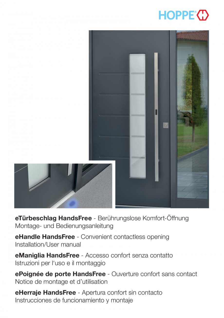
eTürbeschlag HandsFree - Berührungslose Komfort-Öffnung
Montage- und Bedienungsanleitung
eHandle HandsFree - Convenient contactless opening
Installation/User manual
eManiglia HandsFree - Accesso confort senza contatto
Istruzioni per l‘uso e il montaggio
ePoignée de porte HandsFree - Ouverture confort sans contact
Notice de montage et d’utilisation
eHerraje HandsFree - Apertura confort sin contacto
Instrucciones de funcionamiento y montaje
Diese Anleitung muss vom Monteur an den Betreiber weitergegeben werden!
These instructions must be passed from the person responsible for mounting to
the operator!
L'installatore deve trasmettere le presenti istruzioni al gestore!
Ces instructions doivent être transmises par l'installateur à l'utilisateur final !
¡El montador debera entregar estas instrucciones al propietario!
Hersteller/Manufacturer/Produttore/Fabricant/Fabricante
HOPPE AG
Am Plausdorfer Tor 13
DE-35260 Stadtallendorf
Tel. +49 6428 932-0
Fax +49 6428 932-220
info.de@h
oppe.com
www.hoppe.com
Technische Änderungen vorbehalten!
We reserve the right to make technical changes!
Si riserva il diritto di apportare modifiche tecniche!
Sous réserve de modifications techniques !
¡Puede estar sujeto a cambios técnicos!
2
Inhalt/Content/Indice/Sommaire/Índice
eTürbeschlag HandsFree – Deutsch
Seite 5 – 26
eManiglia HandsFree – Italiano
English
Page 27 – 48
Italiano
27
27
28
29
31
32
43
43
45
46
46
46
46
47
47
48
Français
1
Safety notices . . . . . . . . . . . . . . . . . . . . . . . . . . . . . . . . . . . . . . . . . . . . . . . . . . . . . . . . . . . . . . . . . . . . . . . . .
2
Intended use . . . . . . . . . . . . . . . . . . . . . . . . . . . . . . . . . . . . . . . . . . . . . . . . . . . . . . . . . . . . . . . . . . . . . . . . .
3
Scope of delivery . . . . . . . . . . . . . . . . . . . . . . . . . . . . . . . . . . . . . . . . . . . . . . . . . . . . . . . . . . . . . . . . . . . . . .
4
Product description and function
. . . . . . . . . . . . . . . . . . . . . . . . . . . . . . . . . . . . . . . . . . . . . . . . . . . . . . . . . .
5
Notes on mounting and electrical connection . . . . . . . . . . . . . . . . . . . . . . . . . . . . . . . . . . . . . . . . . . . . . . . .
6 Mounting . . . . . . . . . . . . . . . . . . . . . . . . . . . . . . . . . . . . . . . . . . . . . . . . . . . . . . . . . . . . . . . . . . . . . . . . . . . .
7 Start-up . . . . . . . . . . . . . . . . . . . . . . . . . . . . . . . . . . . . . . . . . . . . . . . . . . . . . . . . . . . . . . . . . . . . . . . . . . . . .
8 Configuration . . . . . . . . . . . . . . . . . . . . . . . . . . . . . . . . . . . . . . . . . . . . . . . . . . . . . . . . . . . . . . . . . . . . . . . . .
9 Operation . . . . . . . . . . . . . . . . . . . . . . . . . . . . . . . . . . . . . . . . . . . . . . . . . . . . . . . . . . . . . . . . . . . . . . . . . . .
10 Spare parts . . . . . . . . . . . . . . . . . . . . . . . . . . . . . . . . . .
. . . . . . . . . . . . . . . . . . . . . . . . . . . . . . . . . . . . . . . .
11 Technical Data . . . . . . . . . . . . . . . . . . . . . . . . . . . . . . . . . . . . . . . . . . . . . . . . . . . . . . . . . . . . . . . . . . . . . . . .
12 Disposal . . . . . . . . . . . . . . . . . . . . . . . . . . . . . . . . . . . . . . . . . . . . . . . . . . . . . . . . . . . . . . . . . . . . . . . . . . . . .
13 CE confirmity . . . . . . . . . . . . . . . . . . . . . . . . . . . . . . . . . . . . . . . . . . . . . . . . . . . . . . . . . . . . . . . . . . . . . . . . .
14 Troubleshooting . . . . . . . . . . . . . . . . . . . . . . . . . . . . . . . . . . . . . . . . . . . . . . . . . . . . . . . . . . . . . . . . . . . . . . .
15 Replacing a transponder battery . . . . . . . . . . . . . . . . . . . . . . . . . . . . . . . . . . . . . . . . . . . . . . . . . . . . . . . . . . .
16 Guarantee . . . . . . . . . . . . . . . . . . . . . . . . . . . . . . . . . . . . . . . . . . . . . . . . .
. . . . . . . . . . . . . . . . . . . . . . . . . .
Español
eHandle HandsFree – English
Deutsch
1
Sicherheitshinweise . . . . . . . . . . . . . . . . . . . . . . . . . . . . . . . . . . . . . . . . . . . . . . . . . . . . . . . . . . . . . . . . . . . . . 5
2
Bestimmungsgemäße Verwendung . . . . . . . . . . . . . . . . . . . . . . . . . . . . . . . . . . . . . . . . . . . . . . . . . . . . . . . . . 5
3 Lieferumfang . . . . . . . . . . . . . . . . . . . . . . . . . . . . . . . . . . . . . . . . . . . . . . . . . . . . . . . . . . . . . . . . . . . . . . . . . . 6
4
Produktbeschreibung und Funktionsweise . . . . . . . . . . . . . . . . . . . . . . . . . . . . . . . . . . . . . . . . . . . . . . . . . . . . 7
5
Hinweise zu Montage und elektrischem Anschluss . . . . . . . . . . . . . . . . . . . . . . . . . . . . . . . . . . . . . . . . . . . . . 9
6 Montage . . . . . . . . . . . . . . . . . . . . . . . . . . . . . . . . . . . . . . . . . . . . . . . . . . . . . . . . .
. . . . . . . . . . . . . . . . . . . . 10
7 Erst-Inbetriebnahme . . . . . . . . . . . . . . . . . . . . . . . . . . . . . . . . . . . . . . . . . . . . . . . . . . . . . . . . . . . . . . . . . . . . 21
8 Konfiguration . . . . . . . . . . . . . . . . . . . . . . . . . . . . . . . . . . . . . . . . . . . . . . . . . . . . . . . . . . . . . . . . . . . . . . . . . 21
9 Bedienung . . . . . . . . . . . . . . . . . . . . . . . . . . . . . . . . . . . . . . . . . . . . . . . . . . . . . . . . . . . . . . . . . . . . . . . . . . . 23
10 Ersatzteile . . . . . . . . . . . . . . . . . . . . . . . . . . . . . . . . . . . . . . . . . . . . . . . . . . . . . . . . . . . . . . . . . . . . . . . . . . . . 24
11 Technische Daten . . . . . . . . . . . . . . . . . . . . . . . . . . . . . . . . . . . . . . . . . . . . . . . . . . . . . . . . . . . . . . . . . . . . . . 24
12 Entsorgung . . . . . . . . . . . . . . . . . . . . . . . . . . . . . . . . . . . . . . . . . . . . . . . . . . . . . . . . . .
. . . . . . . . . . . . . . . . 24
13 CE-Konformität . . . . . . . . . . . . . . . . . . . . . . . . . . . . . . . . . . . . . . . . . . . . . . . . . . . . . . . . . . . . . . . . . . . . . . . 24
14 Fehlerbehebung . . . . . . . . . . . . . . . . . . . . . . . . . . . . . . . . . . . . . . . . . . . . . . . . . . . . . . . . . . . . . . . . . . . . . . 25
15 Batterie eines Transponders tauschen . . . . . . . . . . . . . . . . . . . . . . . . . . . . . . . . . . . . . . . . . . . . . . . . . . . . . . 25
16 Garantie . . . . . . . . . . . . . . . . . . . . . . . . . . . . . . . . . . . . . . . . . . . . . . . . . . . . . . . . . . . . . . . . . . . . . . . . . . . . 26
Pagina 49 – 70
1
Istruzioni di sicurezza . . . . . . . . . . . . . . . . . . . . . . . . . . . . . . . . . . . . . . . . . . . . . . . . . . . . . . . . . . . . . . . . . . .
2
Utilizzo conforme alle prescrizioni . . . . . . . . . . . . . . . . . . . . . . . . . . . . . . . . . . . . . . . . . . . . . . . . .
. . . . . . . . .
3 Fornitura . . . . . . . . . . . . . . . . . . . . . . . . . . . . . . . . . . . . . . . . . . . . . . . . . . . . . . . . . . . . . . . . . . . . . . . . . . . . .
4
Descrizione del prodotto e funzionamento . . . . . . . . . . . . . . . . . . . . . . . . . . . . . . . . . . . . . . . . . . . . . . . . . . .
5
Indicazioni su montaggio e collegamento elettrico . . . . . . . . . . . . . . . . . . . . . . . . . . . . . . . . . . . . . . . . . . . . .
6 Montaggio . . . . . . . . . . . . . . . . . . . . . . . . . . . . . . . . . . . . . . . . . . . . . . . . . . . . . . . . . . . . . . . . . . . . . . . . . . .
7
Prima messa in funzione . . . . . . . . . . . . . . . . . . . . . . . . . . . . . . . . . . . . . . . . . . . . . . . . . . . . . . . . . . . . . . . . .
8 Configurazione . . . . . . . . . . . . . . . . . . . . . . . . . . . . . . . . . . . . . . . . . . . . . . . . . . . . . . . . . . . . . . . . . . . . . . .
9 Comando . . . . . . . . . . . . . . . . .
. . . . . . . . . . . . . . . . . . . . . . . . . . . . . . . . . . . . . . . . . . . . . . . . . . . . . . . . . .
10 Ricambi . . . . . . . . . . . . . . . . . . . . . . . . . . . . . . . . . . . . . . . . . . . . . . . . . . . . . . . . . . . . . . . . . . . . . . . . . . . . .
11 Dati tecnici . . . . . . . . . . . . . . . . . . . . . . . . . . . . . . . . . . . . . . . . . . . . . . . . . . . . . . . . . . . . . . . . . . . . . . . . . . .
12 Smaltimento . . . . . . . . . . . . . . . . . . . . . . . . . . . . . . . . . . . . . . . . . . . . . . . . . . . . . . . . . . . . . . . . . . . . . . . . . .
13 Conformità CE . . . . . . . . . . . . . . . . . . . . . . . . . . . . . . . . . . . . . . . . . . . . . . . . . . . . . . . . . . . . . . . . . . . . . . . .
14 Eliminazione degli errori . . . . . . . . . . . . . . . . . . . . . . . . . . . . . . . . . . . . . . . . . . . . . . . . . . . . . . . . . . . . . . . . .
15 Sostituzione della batteria di un transponder . . . . . . . .
. . . . . . . . . . . . . . . . . . . . . . . . . . . . . . . . . . . . . . . . .
16 Garanzia . . . . . . . . . . . . . . . . . . . . . . . . . . . . . . . . . . . . . . . . . . . . . . . . . . . . . . . . . . . . . . . . . . . . . . . . . . . .
49
49
50
51
53
54
65
65
67
68
68
68
68
69
69
70
3
Inhalt/Content/Indice/Sommaire/Índice
ePoignée de porte HandsFree – Français
Page 71 – 92
1
Consignes de sécurité . . . . . . . . . . . . . . . . . . . . . . . . . . . . . . . . . . . . . . . . . . . . . . . . . . . . . . . . . . . . . . . . . .
2
Utilisation conforme . . . . . . . . . . . . . . . . . . . . . . . . . . . . . . . . . . . . . . . . . . . . . . . . . . . . . . . . . . . . . . . . . . . .
3
Contenu de l’emballage . . . . . . . . . . . . . . . . . . . . . . . . . . . . . . . . . . . . . . . . . . . . . . . . . . . . . . . . . . . . . . . . .
4
Description du produit et fonctionnement . . . . . . . . . . . . . . . . . . . . . . . . . . . . . . . . . . . . . .
. . . . . . . . . . . . . .
5
Consignes relatives au montage et au raccordement électrique . . . . . . . . . . . . . . . . . . . . . . . . . . . . . . . . . . .
6 Montage . . . . . . . . . . . . . . . . . . . . . . . . . . . . . . . . . . . . . . . . . . . . . . . . . . . . . . . . . . . . . . . . . . . . . . . . . . . . .
7
Première mise en service . . . . . . . . . . . . . . . . . . . . . . . . . . . . . . . . . . . . . . . . . . . . . . . . . . . . . . . . . . . . . . . .
8 Configuration . . . . . . . . . . . . . . . . . . . . . . . . . . . . . . . . . . . . . . . . . . . . . . . . . . . . . . . . . . . . . . . . . . . . . . . . .
9 Utilisation . . . . . . . . . . . . . . . . . . . . . . . . . . . . . . . . . . . . . . . . . . . . . . . . . . . . . . . . . . . . . . . . . . . . . . . . . . . .
10 Pièces de rechange . . . . . . . . . . . . . . . . . . . . . . . . . . . . . . . . . . . . . . . . . . . . . . . . . . . . . . . . . . . . . . . . . . . .
11 Caractéristiques te
chniques . . . . . . . . . . . . . . . . . . . . . . . . . . . . . . . . . . . . . . . . . . . . . . . . . . . . . . . . . . . . . .
12 Recyclage . . . . . . . . . . . . . . . . . . . . . . . . . . . . . . . . . . . . . . . . . . . . . . . . . . . . . . . . . . . . . . . . . . . . . . . . . . .
13 Conformité CE . . . . . . . . . . . . . . . . . . . . . . . . . . . . . . . . . . . . . . . . . . . . . . . . . . . . . . . . . . . . . . . . . . . . . . . .
14 Dépannage . . . . . . . . . . . . . . . . . . . . . . . . . . . . . . . . . . . . . . . . . . . . . . . . . . . . . . . . . . . . . . . . . . . . . . . . . .
15 Changement de la pile d’un transpondeur . . . . . . . . . . . . . . . . . . . . . . . . . . . . . . . . . . . . . . . . . . . . . . . . . . .
16 Garantie . . . . . . . . . . . . . . . . . . . . . . . . . . . . . . . . . . . . . . . . . . . . . . . . . . . . . . . . . . . . . . . . . . . . . . . . . . . .
eHerraje HandsFree – Español
71
71
72
73
75
76
87
87
89
9
0
90
90
90
90
92
92
Página 93 – 114
1
Indicaciones de seguridad . . . . . . . . . . . . . . . . . . . . . . . . . . . . . . . . . . . . . . . . . . . . . . . . . . . . . . . . . . . . . . . 93
2
Uso previsto . . . . . . . . . . . . . . . . . . . . . . . . . . . . . . . . . . . . . . . . . . . . . . . . . . . . . . . . . . . . . . . . . . . . . . . . . . 93
3
Volumen de suministro . . . . . . . . . . . . . . . . . . . . . . . . . . . . . . . . . . . . . . . . . . . . . . . . . . . . . . . . . . . . . . . . . . 94
4
Descripción del producto y funcionamiento . . . . . . . . . . . . . . . . . . . . . . . . . . . . . . . . . . . . . . . . . . . . . . . . . . 95
5
Notas para el montaje y la conexión eléctrica . . . . . . . . . . . . . . . . . . . . . . . . . . . . . . . . . . . . . . . . . . . . . . . . 97
6 Montaje . . . . . . . . . . . . . . . . . . . . . . . . . . . . . . . . . . . . . . . . . . . . . . . . . . . . . . . . . . . . . . . . . . . . . . . . . . . . . 98
7
Pr
imera puesta en servicio . . . . . . . . . . . . . . . . . . . . . . . . . . . . . . . . . . . . . . . . . . . . . . . . . . . . . . . . . . . . . . 109
8 Configuración . . . . . . . . . . . . . . . . . . . . . . . . . . . . . . . . . . . . . . . . . . . . . . . . . . . . . . . . . . . . . . . . . . . . . . . 109
9 Manejo . . . . . . . . . . . . . . . . . . . . . . . . . . . . . . . . . . . . . . . . . . . . . . . . . . . . . . . . . . . . . . . . . . . . . . . . . . . . 111
10 Piezas de repuesto . . . . . . . . . . . . . . . . . . . . . . . . . . . . . . . . . . . . . . . . . . . . . . . . . . . . . . . . . . . . . . . . . . . . 112
11 Datos técnicos . . . . . . . . . . . . . . . . . . . . . . . . . . . . . . . . . . . . . . . . . . . . . . . . . . . . . . . . . . . . . . . . . . . . . . . 112
12 Reciclaje . . . . . . . . . . . . . . . . . . . . . . . . . . . . . . . . . . . . . . . . . . . . . . . . . . . . . . . . . . . . . . . . . . . . . . . . . . . . 112
13 Conformidad CE
. . . . . . . . . . . . . . . . . . . . . . . . . . . . . . . . . . . . . . . . . . . . . . . . . . . . . . . . . . . . . . . . . . . . . 112
14 Corrección de errores . . . . . . . . . . . . . . . . . . . . . . . . . . . . . . . . . . . . . . . . . . . . . . . . . . . . . . . . . . . . . . . . . 112
15 Cambio de la pila de un transpondedor . . . . . . . . . . . . . . . . . . . . . . . . . . . . . . . . . . . . . . . . . . . . . . . . . . . . 114
16 Garantía . . . . . . . . . . . . . . . . . . . . . . . . . . . . . . . . . . . . . . . . . . . . . . . . . . . . . . . . . . . . . . . . . . . . . . . . . . . 114
4
1 Sicherheitshinweise
In Ihrem eigenen Interesse
Beachten und befolgen Sie diese Sicherheitshinweise genau, um Gefahren und Schäden für Mensch und Sachwerte auszuschließen! Die Montage darf nur durch qualifiziertes
Fachpersonal erfolgen!
•
Gefahr durch elektrischen Strom! Der Anschluss darf nur durch elektrotechnisch
unterwiesene Personen oder Elektrofachkräft
e erfolgen.
• Vor jeder Montage, Reparatur, Wartungs- oder Einstellarbeit alle zugehörigen Stromkreise
spannungsfrei schalten und gegen unbeabsichtigtes Wiedereinschalten absichern.
• Die jeweils lokal geltenden Montage- und Installationsbestimmungen, Richtlinien und Vorschriften einhalten. Das gilt insbesondere für VDE-Richtlinien und -Vorschriften, z. B. Richtlinie über elektrische Verriegelungssysteme von Türen in Rettungswegen.
• Bauseitig muss eine primärseitige Trennvorrichtung des Versorgungsstromkreises und eine
geeignete Schutzeinrichtung (Sicherung) bestehen.
• Bei der Kabelführung scharfe Kanten, das Einklemmen bzw. Quetschen von Kabeln oder Zug
auf den Leitungen vermeiden. Kabel nicht knicken und nicht anbohren. Auf korrekten Sitz der
Steckverbinder achten.
•
Gefahr durch optische Strahlung! Nicht in die LED des Lichtpunktes blicken.
• Bei unsachgemäßem Einsatz, unsachgemäßer Montage oder Installation sowie bei Verwendung von nicht originalen
Zubehörteilen wird keine Haftung übernommen!
• Aus Sicherheits- und Zulassungsgründen (CE) ist das eigenmächtige Umbauen und/
oder Verändern des Produkts nicht gestattet. In diesem Fall erlischt die Gewährleistung.
• Bewahren Sie die Administrations-Karte und sämtliche Schattenkarten an einem sicheren
Ort auf. Treffen Sie bei Verlust eines Transponders oder einer Zutrittskarte die in dieser Anleitung genannten Maßnahmen.
2 Bestimmungsgemäße Verwendung
Der eTürbeschlag HandsFree ist für die Nutzung im privaten Bereich vorgesehen und dient
dazu, eine Haustür durch Mitführen eines Transponders und einer Wischbewegung mit dem
Fuß durch einen Lichtpunkt hinweg zu öffnen. Ein Öffnen ist außerdem mittels einer vor das
Funkmodul gehaltenen Zutritts-Karte vorgesehen. Das Öffnen erfolgt durch ein Motorschloss,
das nicht Teil des Produktes ist, aber von diesem angesteuert wird.
Das Produkt darf nur zu dem hier beschriebenen Zweck verwendet werden. Jede andere
Verwendung i
st nicht bestimmungsgemäß und damit unzulässig.
5
Deutsch
Lesen Sie diese Anleitung sorgfältig durch und bewahren Sie sie griffbereit auf!
3 Lieferumfang
1 Bügelgriff mit Funkmodul, 2 Befestigungssschrauben, 2 Gewindeschrauben
2 Steuerungs-Einheit mit Türgriff, Führungsring, Abdeckring,
1 Gewindeschraube
3 8 Karten:
- Administrations-Karte (Administration Card)
- Konfigurations-Karte (Configuration Card)
- 2 Zutritts-Karten (Entry Cards) mit jeweils einer Schatten-Karte (Shadow Card)
- 2 Transponder-Schatten-Karten
4 2 Transponder
5 Y-Kabel zur Verbindung mit dem Motorschloss
2
1
Aluminium
Kunststoff
4
5
3
Funkmodul
2
Holz
4
5
LED für
Lichtpunkt
6
3
1 Bügelgriff
Der Bügelgriff enthält das Funkmodul mit RF-Lese-Empfangseinheit für die Transponder und
Karten. Außerdem, am unteren Ende des Bügelgriffs, die LED zur Erzeugung des Lichtpunktes und die Sensorik zur Bewegungs-Erkennung.
Sämtliche in diesem Dokument beschriebenen Konfigurationen werden am Funkm
odul vorgenommen.
2 Steuerungs-Einheit
Die Steuerungs-Einheit unterstützt die Außeneinheit bei der Ortung eines Transponders oder
einer Zutritts-Karte. Bei einem Verlust der Administrations-Karte muss die Steuerungs-Einheit
als gepaartes Teil mit ausgetauscht werden.
Die Steuerungs-Einheit bietet keine Visualisierungsmöglichkeiten für Rückmeldungen.
3 Administrations-Karte
Der eTürbeschlag HandsFree bildet eine gepaarte Einheit mit der Administrations-Karte. Diese
Administrations-Karte wird bei ihrem ersten Lesevorgang am Funkmodul mit dem System
gepaart.
Nach diesem Vorgang bedeutet ein Verlust der Administrations-Karte den kompletten Tausch
von Steuerungs-Einheit und Administrations-Karte. Aus Sicherheitsgründen werden keine Daten zur Administrations-Karten-Codierung aufgezeichnet. Daher muss das neue Set genauso
gepaart werden, wie ein neues Bügelgriff-System. Ein bereits gepaartes System reagiert nicht
auf weitere Administrations-Karten des gleichen Systems.
3 Konfigurati
ons-Karte
Die Konfigurations-Karte dient zur farblichen Anpassung des Lichtpunktes an das Gebäude
und den persönlichen Geschmack des Hausbesitzers.
Zur Auswahl stehen 4 mögliche Farben.
4 Transponder und 3 Schatten-Karte
Im Set sind zwei aktive Transponder und die jeweils passende Schatten-Karte enthalten.
Im Auslieferungszustand sind diese noch nicht an dem Bügelgriff angelernt. Zusätzlich zu den
mitgelieferten Transpondern können weitere erworben und angelernt werden.
Es können bis zu 500 Transponder oder Karten angelernt werden.
Eine Schatten-Karte ist werksseitig mit einem Transponder gepaart und dient dazu, den
Transponder anzulernen, oder diesen, im Falle eines Verlustes, wieder zu löschen.
7
Deutsch
4 Produktbeschreibung und Funktionsweise
Das System ermöglicht die berührungslose Öffnung einer Haustür durch eine Fußbewegung
durch einen vom Bügelgriff zum Boden erzeugten Lichtpunkt. Damit ist es möglich, die Haustür zu öffnen, ohne eine Hand frei zu haben. E
in berechtigter Transponder wird beim Annähern
an die Tür automatisch erkannt und das System aktiviert den Lichtpunkt. Zum Öffnen mit einer
Zutritts-Karte wird diese vor das Funkmodul gehalten, um die Tür zu öffnen.
3 Zutritts-Karten und Schatten-Karten
Eine Zutritts-Karte ist der „Schlüssel“ eines berechtigten Benutzers zur berührungslosen Türöffnung. Für die Zutritts-Karten gelten die gleichen Eigenschaften, wie die eines Transponders;
mit dem Unterschied, dass die Funktion der Türöffnung nicht aus einer Distanz ausgelöst wird,
sondern nur aus nächster Nähe zum Funkmodul.
Wichtig: Sicherheitsabstand beachten!
Um ein unabsichtliches Öffnen der Tür zu vermeiden, bewahren Sie den Transponder nicht
in der Nähe der betreffenden Tür auf. Der Abstand zum Funkmodul sollte mindestens 2 m
betragen.
8
5 Hinweise zu Montage und elektrischem Anschluss
•
Vorsicht! Bei der Montage darauf achten, dass Sie die Kabel nicht beschädigen,
knicken oder einklemmen! Darauf
achten, dass ein Biegeradius des dreifachen Kabeldurchmessers nicht unterschritten wird.
• Beim Anschluss zum Motorschloss beachten Sie das zugehörige Anschluss-Schema (siehe Kapitel 6, Montageschritt 11) sowie ggf. die Montageanleitung des Motorschloss-Herstellers.
• Steuerungs-Einheit und Administrations-Karte gehören zusammen und sind nicht einzeln
austauschbar.
Montage und Anschluss:
1. Die Komponenten des Beschlags werden mit vormontierten Kabeln ausgeliefert. Das Kabel des Bügelgriffs wird, wie in den folgenden Abbildungen gezeigt, durch das Türblatt eingefädelt, danach wird der Bügelgriff montiert. Das Kabel der Steuerungs-Einheit wird durch
das Griffloch nach unten durch das Türblatt geführt (Montageschritt 9).
2. Die Kabelenden von Bügelgriff und Steuerungs-Einheit werden mittels Steckverbindern mit
dem Y-Kabel verbunden. Dabei ist auf eine korrekte Ausrichtung zu achten (Montageschritt
10). Die Steckverbinder müssen ohne großen Kraftaufwand einrasten. Das d
ritte Kabelende
des Y-Kabels wird mit dem Motorschloss verbunden (Montageschritt 11).
3. Prüfen Sie nach Einsetzen der Schlosseinheit die korrekte Verkabelung gemäß des Montageschrittes in Teil G. Damit vermeiden Sie, dass Sie im Falle eines Verdrahtungsfehlers
Komponenten wieder demontieren müssen.
9
Deutsch
Allgemeine Hinweise:
6 Montage
A
E5091GC
10
E5092RGC
E5092LGC
Deutsch
B
11
C
12
Deutsch
D
13
E
14
Deutsch
F
15
G
MS
Kabel nicht
knicken
+
Signal
+
Signal
MS
MS
16
GR
GR
WH
WH
YE
YE
BN
BN
Aderkennzeichnung
nach DIN IEC 60757:
BN = braun (+VCC)
YE = gelb (GND)
GR = grün (pot.-frei)
WH = weiß (pot.-frei)
MS = Motorschloss
Deutsch
H
Prüfen! Nach Schritt 12 Spannungsversorgung herstellen und LED des Funkmoduls prüfen:
Bei korrekter Verdrahtung leuchtet die LED des Funkmoduls kurz (200 ms) grün auf. Sollte das
grüne Signal nicht erscheinen, gehen Sie wie hier beschrieben vor:
1. Trennen Sie die Spannungsversorgung.
2. Kabelver
bindungen gemäß den Schritten 10 und 11 sowie den Zustand der Kabel prüfen
und Verbindungen ggf. korrigieren. Beschädigungen instand setzen.
3. Schlosseinheit gemäß Schritt 12 wieder einsetzen.
4. Spannungsversorgung herstellen und LED des Funkmoduls prüfen: Die LED leuchtet bei
korrekter Verdrahtung 1x kurz grün (200 ms).
Beachten Sie dazu auch das Kapitel 14 Fehlerbehebung.
17
I
18
6 mm
Deutsch
J
19
20
8 Konfiguration
Zur Konfiguration die betreffenden Karten wie nachfolgend beschrieben vor das Funkmodul
halten. Erfolgt nicht sofort eine Reaktion, erkennbar am Blinken oder Leuchten der LED, die
Position der betreffenden Karte vor dem Funkmodul verändern, bis eine Reaktion erfolgt.
Für alle im folgenden beschriebenen Konfigurationen wird als Voraussetzung immer der Administrations-Modus gestartet, wie unter 8.1 beschrieben.
Wichtig
Bei der Konfirguration mit der Administrations-Karte darf sich kein Transponder im Empfangsbereich befinden!
8.1 Administrations-Mo
dus
Im Administrations-Modus können Sie:
• Transponder oder Zutritts-Karten an- oder auslernen
• die Farbe des Lichtpunktes wählen
Administrations-Modus starten
Die Administrations-Karte an das Funkmodul halten, bis die LED langsam blau blinkt.
8.2 Transponder oder Zutritts-Karte anlernen
1. Administrations-Modus starten (siehe 8.1)
2. Anlernen: Schatten-Karte des anzulernenden Transponders oder der Zutritts-Karte an das
Funkmodul halten, bis die LED grün leuchtet.
Wenn die LED rot blinkt, wurde der Transponder oder die Zutritts-Karte bereits angelernt.
8.3 Transponder oder Zutritts-Karte auslernen
1. Administrations-Modus starten (siehe 8.1)
2. Auslernen: Schatten-Karte des auszulernenden Transponders oder der Zutritts-Karte an
das Funkmodul halten. Die LED blinkt für ca. 10 Sekunden rot.
21
Deutsch
7 Erst-Inbetriebnahme
Spannungsversorgung einschalten. Das Funkmodul blinkt im Wechsel
rot-blau. Für die Erst-Inbetriebnahme muss die Administrations-Karte
mit der Steuerun
gs-Einheit gepaart werden.
Dazu die Administrations-Karte an das Funkmodul halten. Nach erfolgreicher Paarung erlischt das rot-blaue Leuchtsignal.
Wenn Sie die Karte weiterhin vor das Funkmodul halten, wird der Administrations-Modus, wie in Kapitel 8.1 beschrieben, gestartet.
Das erfolgreiche Auslernen wird nach ca. 10 Sekunden durch das Leuchten der roten LED
bestätigt.
Auslernen abbrechen
Schatten-Karte während des Blinkens, innerhalb von 10 Sekunden, vom Funkmodul entfernen.
Wenn die LED grün leuchtet, wurde der Transponder/die Zutritts-Karte noch nicht angelernt.
8.4 Alle Transponder und Zutritts-Karten auslernen
Wenn Sie Transponder oder Schatten-Karten verlieren, haben Sie die Möglichkeit, zu Ihrer Sicherheit alle angelernten Transponder und Zutritts-Karten gleichzeitig und ohne Verwendung
von Schatten-Karten auszulernen.
1. Administrations-Modus starten (siehe 8.1)
2. ALLE auslernen: Administrations-Karte an das Funkmodul halten, bis die LED rot blinkt (ca.
10 Sekunden).
Das erfolgreiche Auslernen wird nach ca. 10 Sekunden durch das Leuchten der roten LED
bestätigt.
Auslernen abbrechen
Administrations-Karte während des Blinkens, innerhalb von 10 Sekunden, vom Funkmodul entfernen.
8.5 Farbe des Lichtpunktes einstellen
Der Lichtpunkt, der ein empfangenes Transpondersignal anzeigt, kann in der Farbe an die Gegebenheiten der Immobilie oder den persönlichen Geschmack des Benutzers angepasst werden.
1. Administrations-Modus starten (siehe 8.1)
2. Farbwahl: Konfigurations-Karte vor das Funkmodul halten. Der Lichtpunkt durchläuft im 2
Sekunden-Takt die 4 möglichen Farben.
Konfigurations-Karte bei der gewünschten Farbe vom Funkmodul entfernen.
Diese Farbe ist nun aktiv.
22
9 Bedienung
9.1 Tür mit Transponder und Fußbewegung öffnen
Bei Annäherung an die Tür mit dem Transponder wird bei Erkennung durch das System der
Lichtpunkt eingeschaltet. Es ist nicht nötig, den Transponder in der Hand zu halten. Das System reagiert in einem Erkennungsradiu
s von ca. 1 Meter.
Tür öffnen: Den Lichtpunkt durch eine Bewegung unterbrechen, z. B. mit dem Fuß.
Beim Öffnen der Tür blinkt der Lichtpunkt 3x und erlischt dann.
9.2 Tür mit Zutritts-Karte öffnen
Soll die Tür mit einer Zutritts-Karte geöffnet werden, gehen Sie wie nachfolgend beschrieben
vor.
Tür öffnen: Die Zutritts-Karte vor das Funkmodul
halten und ggf. seitwärts hin und her bewegen,
bis der Lichtpunkt 3x kurz blinkt und die Tür geöffnet
wird.
Tipp: Sollte das System nicht sofort reagieren,
variieren Sie die Position der Zutritts-Karte vor dem
Funkmodul, um die ideale Ansprechposition zu
ermitteln.
23
Deutsch
Nachfolgend wird das Öffnen der Tür mit einem Transponder sowie einer Zutritts-Karte erläutert.
10 Ersatzteile
Für Ersatzteile sowie zusätzliche Transponder oder Zutritts-Karten wenden Sie sich bitte
an Ihren HOPPE-Vertriebspartner oder schauen Sie direkt in unseren Produktkatalog unter
www.hoppe.com.
11 Technische Daten
Betriebsspannung:
8 - 24V DC
B
elastbarkeit Schaltkontakt:
24V DC, 1,5 A (max)
Funk-Frequenzen:
125 kHz / 868 MHz
Sendeleistung:
6,3 mW
Verschlüsselung: AES
Maximale Leistungsaufnahme:
0,7 W
Erfassungsbereich des Transponders:
ca. 1 m
Betriebstemperatur:
-20 bis 60 °C
Schutzart:
IP 44
Batterie Transponder:
Typ: CR2450
12 Entsorgung
Das Produkt darf nicht über den normalen Hausmüll entsorgt werden. Sie sind
verpflichtet, Altprodukte an einer Rücknahmestelle für Elektro- und Elektronik-Altgeräte abzugeben.
Informationen, wo Sie Rücknahmestellen für Ihre Altprodukte finden, erhalten Sie
bei Ihrer Stadtverwaltung, den örtlichen Müllentsorgungs-Betrieben oder beim
Händler, bei dem Sie das Produkt erworben haben.
Alte Batterien können Sie unentgeltlich bei den öffentlichen Sammelstellen der Gemeinden
und überall dort abgeben, wo Batterien und Akkus der betreffenden Art verkauft werden.
Altbatterien dürfen Sie nicht über den Hausmüll entsorgen.
13 CE-Konformität
Der eTürbeschlag HandsFree ist
mit dem CE-Zeichen gekennzeichnet.
Die HOPPE AG bestätigt hiermit, dass der Funkanlagentyp der Richtlinie
2014/53/EU entspricht.
Der vollständige Text der EU-Konformitätserklärung ist auf www.hoppe.com im Bereich Service abrufbar.
24
Verlust eines Transponders oder einer Zutritts-Karte
Bei Verlust eines angelernten Transponders oder einer Zutritts-Karte haben Sie die Möglichkeit,
die betreffende Karte gemäß Kapitel 8 auszulernen.
LED des Funkmoduls blinkt rot-gelb = Verdrahtungsfehler
Im Falle eines Verdrahtungsfehlers wird folgende Lichtsequenz angezeigt:
LED blinkt rot-gelb im Wechsel, Leuchtdauer pro Farbe: 1 Sekunde.
Dauer: Bis der Fehler behoben ist.
Maßnahme: Bitte kontaktieren Sie Ihren Händler/Montagebetrieb, bei dem Sie den eTürbeschlag HandsFree erworben haben.
LED des Funkmoduls blinkt rot-blau = Paarungs-Vorgang nicht abgeschlossen
Wenn nach dem Einschalten der Spannungsversorgung erkannt wird, dass beide Einheiten
noch nicht gepaart sind, wird dies mit folgend
er Lichtsequenz angezeigt:
LED blinkt rot-blau im Wechsel, Leuchtdauer pro Farbe: 1 Sekunde.
Maßnahme: Halten Sie die Administrations-Karte an das Funkmodul.
Dauer: Bis das rot-blaue Leuchtsignal erlischt.
Wichtig Stellen Sie sicher, dass die Spannungsversorgung während des PaarungsVorgangs nicht unterbrochen wird!
LED des Funkmoduls blinkt rot = nicht behebbarer Fehler
Liegt ein durch den Nutzer nicht behebbarer Fehler vor, wird diese Lichtsequenz angezeigt:
LED blinkt rot, Blinkfrequenz: An = 1 Sekunde, Aus = 9 Sekunden
Dauer: Bis der Fehler behoben ist.
Maßnahme: Kontaktieren Sie Ihren Händler bzw. Montagebetrieb.
LED des Funkmoduls blinkt rot-lila = Steuerungs-Einheit defekt
Maßnahme: Steuerungs-Einheit muss getauscht werden. Bitte kontaktieren Sie Ihren Händler/
Montagebetrieb.
25
Deutsch
14 Fehlerbehebung
Verlust der Administrations-Karte
Die Administrations-Karte ist fester Bestandteil der zugehörigen Steuerungs-Einheit und funktioniert nicht an anderen Systemen des gl
eichen Typs. Das bedeutet, dass bei einem Verlust
dieser Karte ein Austausch der kompletten Steuerungs-Einheit notwendig ist. Nach dem Austausch der Steuerungs-Einheit muss die neue Administrations-Karte durch Lesen am Funkmodul mit dem System gepaart werden (siehe Kapitel 7).
Bewegungen werden nicht erkannt
Bewegungen werden nur bei vorhandenem Lichtpunkt erkannt. Sollte die Fußbewegung dennoch nicht erkannt werden bzw. unzuverlässig erkannt werden, den Abstand vom unteren
Bügelgriffende zum Boden prüfen (20 bis 50 cm, siehe Kapitel 6, Bild B).
Lichtpunkt wird nicht angezeigt
Mögliche Ursachen: Transponder befindet sich nicht nahe genug an der Tür (ca. 1 m) oder
wurde nicht angelernt.
Maßnahmen: Den Mindestabstand zur Tür beachten (siehe Kapitel 9.1). Transponder anlernen
(siehe Kapitel 8.2).
Transponder wird nicht erkannt
Ursache: Der betreffende Transponder wurde nicht angelernt.
Maßnahme: Transponder anlernen (siehe Kapitel 8).
Ursache: Die Batterie des Transponders ist
leer.
Maßnahme: Batterie erneuern (siehe Kapitel 15).
Die LED des Funkmoduls leuchtet kurz gelb, sobald der entsprechenden Transponder
den Empfangsbereich des Funkmoduls erreicht.
Ursache: Die Batterie des Transponders ist schwach.
Maßnahme: Batterie erneuern (siehe Kapitel 15).
CR2450
15 Batterie eines Transponders tauschen
Öffnen Sie das Batteriefach des Transponders mit einer Münze. Schieben Sie die Batterie seitlich aus der Halterung, wie in der folgenden Abbildung gezeigt. Verwenden sie dazu keinen
Schraubendreher o. ä. Metallgegenstand. Tauschen Sie die Batterie gegen eine neue des gleichen Typs aus (siehe Kapitel Technische Daten). Schließen Sie das Batteriefach.
16 Garantie
Als Hersteller garantieren wir die einwandfreie mechanische Funktion von sachgemäß gebrauchten Tür- und Fenstergriffen von HOPPE für einen Zeitraum von
10 Jahren ab dem Kaufdatum. Für elektronische Bauteile gilt die gesetzliche
Gewährleistung von 24 Monaten.
Unsere detaillierten Garantiebestim
mungen finden Sie unter
www.hoppe.com/guarantee.
26
1 Safety notices
For your own protection
Please read these instructions carefully and keep them to hand!
Please note and follow these safety notices carefully to avoid danger and damage to
people and property! Mounting should only be carried out by a qualified specialist!
Danger due to electric current! Connection should only be undertaken by trained
electrical engineers or electrical specialists.
• Before all mounting, repair, maintenance or installation work, all associated electrical circuits
should be disconnected and prevented from being switched on unintentionally.
• The respective locally applicable mounting and installation provisions, guidelines and regulations should be observed. This applies in particular to VDE directives and regulations, such
as the directive on electronic locking systems of doors in escape routes.
• On site, there must be a supply current disconnecting device on the primary side and a sui
table protective device (fuse).
• When routing cables, avoid sharp edges, trapping or crushing cables or pulling on wires. Do
not kink or drill into the cables. Make sure the connectors fit correctly.
•
Danger due to optical radiation! Do not look into the LED of the light spot.
• We will not accept liability in the case of improper usage, improper mounting or installation, or
if non-original accessories are used!
• Converting and/or modifying the product without authorisation is not permitted for safety and
licensing reasons (CE). This would render claims under warranty null and void.
• Keep the administration card and all shadow cards in a safe place. If a transponder or entry
card is lost, follow the instructions in this manual.
2 Intended use
The eHandle HandsFree is intended for use in the private sector and is used to open an entrance door when a person carrying a transponder makes a swiping motion through a light
spot with their foot. It is also possible to open
the door using an entry card held in front of the
radio module. The door is opened by means of a motor lock, which is not part of the product,
but is controlled by it.
The product may only be used for the purpose described here. Any other use is not intended
and therefore prohibited.
27
English
•
3 Scope of delivery
1 Pull handle with radio module, 2 fixing screws, 2 thread screws
2 Control unit with door handle, washers, cover ring,
1 thread screw
3 8 cards:
- Administration card
- Configuration card
- 2 entry cards, each with its own shadow card
- 2 transponder shadow cards
4 2 transponders
5 Y-cable for connecting to the motor lock
2
1
Aluminium
Polyamide
4
5
3
Radio module
2
Wood
4
5
LED for
light spot
28
3
4 Product description and function
The system allows contactless opening of an entrance door by moving a foot through a light
spot generated from the pull handle to the ground. This makes it possible to open the entrance
door hands-free. An authorised tra
nsponder is automatically detected when approaching the
door and the system activates the light spot. To open the door with an entry card, it must be
held in front of the radio module.
2 Control unit
The control unit supports the external unit when detecting a transponder or an entry card. If
the administration card is lost, the control unit must be replaced as a paired part.
The control unit does not offer any visualisation capabilities for feedback.
3 Administration card
The eHandle HandsFree forms a paired unit with the administration card. This administration
card is paired with the system when it is first read on the radio module.
After this process, losing the administration card requires the complete replacement of the
control unit and administration card. For security reasons, no data on the administration card
encoding is logged. For that reason, the new set must be paired in exactly the same way as
a new pull handle system. An already paired system will not respond to other
administration
cards of the same system.
3 Configuration card
The configuration card is used to adjust the colour of the light spot to the building and the
personal taste of the homeowner.
There are four possible colours to choose from.
4 Transponder and 3 shadow card
The set contains two active transponders, each with a matching shadow card.
When delivered, these are not yet programmed to the pull handle. In addition to the supplied
transponders, more can be purchased and programmed.
Up to 500 transponders or cards can be programmed.
A shadow card is paired with a transponder by the manufacturer and is used to programme
the transponder, or, if the transponder is lost, to delete it.
3 Entry cards and shadow cards
An entry card is the “key” for an authorised user to contactlessly open the door. Entry cards
have the same characteristics as a transponder, with the difference that the door opening is
not triggered from a distance, but only in close proximity to the radio module.
29
En
glish
1 Pull handle
The pull handle contains the radio module with RF reader/receiver unit for the transponders
and cards. In addition, at the bottom end of the pull handle, there is an LED for generating the
light spot and sensors for motion detection.
All configurations described in this document are performed using the radio module.
Important: Please observe the safety distance!
To avoid accidentally opening the door, do not store the transponder near the relevant door.
The distance from the radio module should be at least 2 m.
30
5 Notes on mounting and electrical connection
General information:
•
Caution! During mounting, take care not to damage, kink or trap any cables! Make
sure that the bend radius is no less than three times the cable diameter.
• When connecting to the motor lock, please note the associated connection diagram (see
Chapter 6, Assembly step 11) and, if necessary, the mounting instructions of the motor lock
manufacturer.
Mounting and connection:
1
. The components of the hardware are delivered with pre-mounted cables. The cable of the
pull handle is routed through the door leaf, as shown in the following figures, after which
the pull handle is mounted. The cable of the control unit is routed through the handle hole
downward through the door leaf (Mounting step 9).
2. The cable ends of the pull handle and control unit are connected to the Y-cable using plug
connectors. Please ensure that they are in the correct orientation (Mounting step 10). The
connectors should engage without much force being applied. The third cable end of the
Y-cable is connected to the motor lock (Mounting step 11).
3. After inserting the lock unit, check that the wiring is correct according to the mounting step
in part G. This will prevent you having to disassemble components in the event of a wiring
error.
31
English
• The control unit and administration card belong together and may not be replaced separately.
6 Mounting
A
E5091GC
32
E5092RGC
E5092LGC
English
B
33
C
34
English
D
35
E
36
English
F
37
G
MS
Do not
kink cables!
+
Signal
+
Signal
MS
38
MS
GR
GR
WH
WH
YE
YE
BN
BN
Core identification
in accordance with
DIN IEC 60757:
BN = brown (+VCC)
YE = yellow (GND)
GR = green (pot.-free)
WH = white (pot.-free)
MS = Motor lock
English
H
Check! After step 12, connect to the power supply and check the LED of the radio module: If
the wiring is correct, the LED of the radio module briefly lights up green (200 ms). If the green
signal does not appear, take the following steps:
1. Disconnect the power supply.
2. Check cable connections in accordance with steps 10 and 11 as well as the condition of
the cables and correct the connections if necessary. Repair any damage.
3. Insert the lock unit again in accordance with step 12.
4. Connect to the power supply and check the LED of the radio module: If the wiring is correct, the LED briefly lights up green just once (200 ms).
Please also refer
to Chapter 14 Troubleshooting.
39
I
40
6 mm
English
J
41
42
7 Start-up
8 Configuration
To configure, hold the relevant cards in front of the radio module as described below. If no
response occurs immediately, indicated by the LED flashing or lighting up, change the position
of the relevant card in front of the radio module until a response occurs.
For all configurations described below, administration mode should always be
started as described under 8.1.
Important
When configuring with the administration card, there must not be any transponders in the
reception range!
8.1 Administration mode
In administration mode you can:
• Programme and clear transponders or entry cards
• Choose the colour of the light spot
Start administration mode
Hold the administration card close to the radio module until the LED flashes blue slowly.
8.2 Programming the transponder or entry card
1. Start administration mode (see 8.1)
2. Programming: Hold the shadow card of the transponder or e
ntry card to be programmed
close to the radio module until the LED lights up green.
If the LED flashes red, the transponder or the entry card has already been programmed.
8.3 Clearing the transponder or entry card
1. Start administration mode (see 8.1)
2. Clearing: Hold the shadow card of the transponder or entry card to be cleared close to the
radio module. The LED will flash red for approximately 10 seconds.
43
English
Switch on the power supply. The radio module flashes alternately red
and blue. For start-up, the administration card must be paired with the
control unit.
To do this, hold the administration card close to the radio module. After
successful pairing the red and blue light signal will go out.
If you continue to hold the card in front of the radio module, administration mode is started, as described in Chapter 8.1.
Successful clearing is confirmed after approximately 10 seconds by the red LED lighting up.
Cancel clearing
Remove the shadow card from the radio module
while flashing, within 10 seconds.
If the LED lights up green, the transponder/entry card has not yet been cleared.
8.4 Clearing all transponders or entry cards
If you lose transponders or shadow cards, for your own security you have the option of clearing
all programmed transponders and entry cards at the same time without using shadow cards.
1. Start administration mode (see 8.1)
2. Clear ALL: Hold the administration card close to the radio module until the LED flashes red
(approximately 10 seconds).
Successful clearing is confirmed after approximately 10 seconds by the red LED lighting up.
Cancel clearing
Remove the administration card from the radio module while flashing, within 10 seconds.
8.5 Setting the colour of the light spot
The colour of the light spot, which indicates that a transponder signal has been received, can
be adapted to the conditions of the building or the personal taste of the user.
1. Start administration mode (see 8.1)
2. Choice of colour: Hold the configura
tion card in front of the radio module. The light spot
switches between the four possible colours every two seconds.
Remove the configuration card from the radio module when the desired colour is shown.
This colour is now active.
44
9 Operation
Opening the door with a transponder as well as with an entry card is explained below.
9.1 Opening the door with the transponder and a foot movement
When approaching the door with the transponder, the light spot is switched on when the transponder is detected by the system. It is not necessary to hold the transponder in your hand.
The system responds within a detection radius of approximately 1 metre.
English
Opening the door: Block the light spot with a movement, for example with a foot.
When the door is opened, the light spot flashes three times and then goes out.
9.2 Opening the door with an entry card
To open the door with an entry card, follow the instructions below.
Opening the door: Hold the entry card in front of
the radio module a
nd move it sideways back and
forth if necessary until the light spot flashes briefly
three times and the door is opened.
Tip: If the system does not respond immediately,
vary the position of the entry card in front of the
radio module to determine the ideal response
position.
45
10 Spare parts
For spare parts and additional transponders or entry cards, please contact your HOPPE sales
partner or have a look at our product catalogue directly at www.hoppe.com.
11 Technical data
Operating voltage:
8 – 24V DC
Current-carrying capacity of switch contact: 24V DC, 1.5 A (max)
Radio frequencies:
125 kHz / 868 MHz
Transmission power:
6.3 mW
Encryption: AES
Maximum power consumption:
0.7 W
Detection range of the transponder:
approx. 1 m
Operating temperature:
-20 to 60 °C
Protection class:
IP 44
Transponder battery:
Type: CR2450
12 Disposal
The product should not be disposed of with normal household waste. You are
obliged to dispose of used products at a collection point for use
d electrical and
electronic devices.
Information about collection points for used products is available from your local
authority, from local waste disposal companies or from the shop where you purchased the product.
You can hand in old batteries free of charge at public collection points in local authorities
and wherever batteries of the type in question are sold. Do not dispose of used batteries in
household waste.
13 CE conformity
The eHandle HandsFree is marked with the CE mark.
HOPPE AG herewith confirms that the radio equipment type corresponds to the
Directive 2014/53/EU.
The full text of the EU Declaration of Conformity is available at www.hoppe.com under the
Service section.
46
14 Troubleshooting
Lost administration card
The administration card is an integral part of the associated control unit and does not work on
other systems of the same type. This means that if you lose this card, you will need to replace
the entire control unit. After replacing the control unit, the ne
w administration card must be
paired with the system by reading it on the radio module (see Chapter 7).
LED of the radio module flashes red and yellow = Wiring error
In the event of a wiring error, the following light sequence is displayed:
LED flashes alternately red and yellow, light duration per colour: 1 second.
Duration: Until the defect is corrected.
Action: Please contact your dealer/installing company from which you purchased the eHandle
HandsFree.
LED of radio module flashes red and blue = Pairing process not completed
If, after switching on the power supply, it is detected that the two units have not been paired
yet, this is indicated by the following light sequence:
LED flashes alternately red and blue, light duration per colour: 1 second.
Action: Hold the administration card close to the radio module.
Duration: Until the red and blue light signal goes off.
Important Make sure the power supply is not interrupted during the pairing process!
LED of the radio module flashes re
d = Unrecoverable defect
If there is a defect that cannot be corrected by the user, this light sequence is displayed:
LED flashes red, flash frequency: On = 1 second, Off = 9 seconds
Duration: Until the defect is corrected.
Action: Contact your dealer or installing company.
LED of the radio module flashes red and purple = Control unit defective
Action: Control unit must be replaced. Please contact your dealer/installing company.
47
English
Lost transponder or entry card
If you lose a programmed transponder or an entry card, you have the option to clear the affected
card in accordance with Chapter 8.
Movements are not detected
Movements are only detected when there is a light spot. If foot movements are still not detected
or detection is unreliable, check the distance from the lower end of the pull handle to the ground
(20 to 50 cm, see Chapter 6, Figure B).
Light spot is not displayed
Possible causes: Transponder is not close enough to the door (approximately 1 m) or has not
bee
n programmed.
Actions: Observe the minimum distance from the door (see Chapter 9.1). Programme the transponder (see Chapter 8.2).
Transponder is not detected
Cause: The relevant transponder has not been programmed.
Action: Programme the transponder (see Chapter 8).
Cause: The transponder’s battery is empty.
Action: Replace battery (see Chapter 15).
The LED of the radio module briefly lights up yellow as soon as the corresponding
transponder reaches the reception range of the radio module.
Cause: The transponder’s battery is low.
Action: Replace battery (see Chapter 15).
CR2450
15 Replacing a transponder battery
Open the transponder’s battery compartment with a coin. Slide the battery sideways out of the
holder as shown in the illustration below. Do not use a screwdriver or any similar metal objects
to do this. Replace the battery with a new one of the same type (see Chapter Technical data).
Close the battery compartment.
16 Guarantee
As a manufacturer, we guarantee the flawles
s mechanical function of properly
used HOPPE door and window handles for a period of 10 years from the date of
purchase. A statutory warranty of 24 months applies to electronic components.
Our detailed guarantee conditions can be found at
www.hoppe.com/guarantee.
48
1 Istruzioni di sicurezza
Nel vostro interesse
Leggere attentamente le presenti istruzioni e conservarle a portata di mano!
Attenersi scrupolosamente alle presenti istruzioni di sicurezza per evitare pericoli e danni a persone e beni materiali! Il montaggio deve essere eseguito solo da personale qualificato!
•
Pericolo a causa di corrente elettrica! Il collegamento deve essere eseguito solo
da personale elettrotecnico addestrato o specialisti elettrotecnici.
• Prima di qualsiasi intervento di montaggio, riparazione, manutenzione o regolazione, togliere
tensione da tutti i circuiti e impedirne il reinserimento involontario.
• In loco devono essere presenti un interruttore sul lato primario del circuito di a
limentazione e
un dispositivo di protezione (fusibile) adatto.
• Nella disposizione dei cavi, evitare spigoli vivi, il pizzicamento o lo schiacciamento dei cavi o
una tensione meccanica sugli stessi. Non piegare o forare i cavi. Verificare che i connettori
siano posizionati correttamente.
•
Pericolo a causa delle radiazioni ottiche! Non guardare direttamente il LED del
punto luminoso.
• Non si assume alcuna responsabilità in caso di impiego, montaggio o installazione impropri e
di utilizzo di accessori non originali!
• Per motivi di sicurezza e omologazione (CE) è vietato trasformare e/o modificare autonomamente il prodotto. In questo caso, la garanzia decade.
• Conservare la tessera amministratore e tutte le tessere di cancellazione in un luogo sicuro.
In caso di perdita di un transponder o di una tessera di accesso adottare le misure riportate
in queste istruzioni.
2 Utilizzo conforme alle prescrizioni
La eManiglia HandsFree è destinata all'uso nel settore privato
e serve ad aprire una porta
d'ingresso avendo con sé un transponder e passando il piede su un punto luminoso. È prevista anche la possibilità di apertura tenendo davanti al modulo radio una tessera di accesso.
L'apertura viene effettuata da una serratura motorizzata, che non fa parte del prodotto, ma
viene comandata da esso.
Il prodotto deve essere utilizzato solo per lo scopo qui descritto. Ogni altro uso non è conforme alle prescrizioni ed è quindi vietato.
49
Italiano
• Rispettare eventuali disposizioni di montaggio e installazione, direttive e normative in vigore a
livello locale. Questo vale in particolare per le direttive e le normative VDE, ad es. la direttiva
sui sistemi elettrici di bloccaggio delle porte nelle vie di fuga.
3 Fornitura
1 Maniglione con modulo radio, 2 viti di fissaggio, 2 viti filettate
2 Unità di controllo con maniglia, anello di guida, anello di copertura,
1 vite filettata
3 8 tessere:
- Tessera amministratore (Administation Card)
- Tessera
di configurazione (Configuration Card)
- 2 tessere di accesso (Entry Cards) con ognuna una tessera di cancellazione
(Shadow Card)
- 2 tessere di cancellazione con transponder
4 2 transponder
5 Cavo a Y per il collegamento alla serratura motorizzata
2
1
Alluminio
Plastico
4
5
3
Modulo radio
2
Legno
4
5
LED per il
punto luminoso
50
3
4 Descrizione del prodotto e funzionamento
Il sistema consente l'apertura senza contatto di una porta d'ingresso passando il piede sul
punto luminoso generato sul pavimento dal maniglione. In questo modo si può aprire la porta d'ingresso anche con le mani occupate. Il sistema riconosce il transponder autorizzato
quando si avvicina alla porta e attiva il punto luminoso. Per aprire la porta con una tessera di
accesso, questa deve essere tenuta davanti al modulo radio.
1 Maniglione
Nel maniglione è presente il modulo radio con l'unità di ricezione e lettura RF per il transponder
e le tessere. Inoltre nell'estremità inferiore del maniglione si t
rova il LED per la generazione del
punto luminoso e la sensoristica per il riconoscimento del movimento.
Tutte le configurazioni descritte in questo documento vengono effettuate sul modulo radio.
2 Unità di controllo
3 Tessera amministratore
La eManiglia HandsFree costituisce un'unità accoppiata con la tessera amministratore. L'accoppiamento con il sistema avviene alla prima lettura da parte del modulo radio.
In base a questa procedura, la perdita della tessera amministratore implica la sostituzione
completa dell'unità di controllo e della tessera amministratore. Per motivi di sicurezza sulla
codifica della tessera amministratore non vengono registrati dati. Pertanto il nuovo set deve
essere accoppiato nello stesso modo come per un sistema maniglione nuovo. Un sistema già
accoppiato non reagisce ad altre tessere amministratore dello stesso sistema.
3 Tessera di configurazione
La tessera di configurazione serve ad adattare il colore del punto luminoso all'edificio e al
gusto person
ale del proprietario.
Si può scegliere tra 4 colori.
4 Transponder e 3 tessera di cancellazione (Shadow Card)
Il set comprende due transponder attivi e le corrispondenti tessere di cancellazione (Shadow
Card).
Alla consegna, queste ultime non sono ancora state programmate sul maniglione. In aggiunta
a quelli forniti è possibile acquistare e programmare altri transponder.
È possibile programmare fino a 500 transponder e tessere.
Una tessera di cancellazione (Shadow Card) è accoppiata di fabbrica a un transponder e
serve a programmare il transponder o a cancellarlo in caso di perdita.
51
Italiano
L'unità di controllo supporta l'unità esterna nella localizzazione di un transponder o di una
tessera di accesso. In caso di perdita della tessera amministratore si deve sostituire l'unità di
controllo come componente accoppiata.
L'unità di controllo non consente di visualizzare i segnali di ritorno.
3 Tessere di accesso e tessere di cancellazione (Shadow Card)
Una tessera di acces
so è la "chiave" che un utente autorizzato utilizza per aprire la porta
senza contatto. Per le tessere di accesso valgono le stesse proprietà di un transponder, con
la differenza che l'apertura della porta non viene attivata a distanza, ma solo in prossimità del
modulo radio.
Importante: rispettare la distanza di sicurezza!
Per evitare l'apertura indesiderata della porta, non conservare il transponder in prossimità
della porta interessata. La distanza dal modulo radio deve essere di almeno 2 m.
52
5 Indicazioni su montaggio e collegamento elettrico
Indicazioni generali:
•
Avvertenza! Durante il montaggio, prestare attenzione a non danneggiare, piegare
o pizzicare i cavi! Assicurarsi che il raggio di piegatura non sia meno di tre volte il diametro
del cavo.
• Durante il collegamento alla serratura motorizzata, seguire il rispettivo schema di collegamento (vedere il capitolo 6, passo di montaggio 11) e le istruzioni di montaggio del produttore della serratura motorizzata.
• L'unità di controllo e la tessera amministratore costituiscono un sistema unico e non possono essere sostituite singolarmente.
1. I componenti della maniglia vengono forniti con cavi premontati. Come mostrato nelle seguenti figure, prima viene fatto passare il cavo del maniglione nel pannello porta e poi viene
montato il maniglione. Il cavo dell'unità di controllo viene spinto verso il basso attraverso il
foro maniglia, lungo il pannello porta (passo di montaggio 9).
2. Le estremità del cavo del maniglione e dell'unità di controllo vengono collegate al cavo a Y
tramite dei connettori. Assicurarsi che l'orientamento sia corretto (passo di montaggio 10). I
connettori devono bloccarsi senza dover esercitare una forza eccessiva. La terza estremità
del cavo a Y viene collegata alla serratura motorizzata (passo di montaggio 11).
3. Dopo l'inserimento della serratura, controllare la correttezza del cablaggio secondo il passo
di montaggio nella sezione G. In questo modo si evita di
smontare nuovamente i componenti in caso di errore di cablaggio.
53
Italiano
Montaggio e collegamento:
6 Montaggio
A
E5091GC
54
E5092RGC
E5092LGC
Italiano
B
55
C
56
Italiano
D
57
E
58
Italiano
F
59
G
MS
Non piegare
i cavi!
+
Signal
+
Signal
MS
60
MS
GR
GR
WH
WH
YE
YE
BN
BN
Marcatura dei fili a norma
DIN IEC 60757:
BN = marrone (+VCC)
YE = giallo (GND)
GR = verde (potenziale zero)
WH = bianco (potenziale zero)
MS = serratura motorizzata
Italiano
H
Controllare! Al termine del passo 12, collegare l'alimentazione elettrica e controllare il LED del
modulo radio: se il cablaggio è corretto, il LED del modulo radio si accende brevemente (200 ms)
di colore verde. Se non viene emesso il segnale verde, procedere come descritto qui di seguito:
1. Scollegare l'alimentazione elettrica.
2. Controllare i cavi di collegamento secondo i passi 10 e 11, le loro condizioni e, se necessario, i collegamenti. Riparare i danni.
3. Inserire nuovamente l'unit
à serratura secondo il passo 12.
4. Collegare l'alimentazione elettrica e controllare il LED del modulo radio: se il cablaggio è
corretto, il LED si accende brevemente 1 volta di colore verde (200 ms).
A tal fine prestare attenzione al capitolo 14 Eliminazione degli errori.
61
I
62
6 mm
Italiano
J
63
64
7 Prima messa in funzione
Attivare l'alimentazione elettrica. Il modulo radio lampeggia alternatamente in
rosso/blu. Alla prima messa in funzione la tessera amministratore deve
essere accoppiata all'unità di controllo.
A tal fine tenere la tessera amministratore sul modulo radio. Al termine
dell'accoppiamento il segnale luminoso rosso/blu si spegne.
Continuando a tenere la tessera davanti al modulo radio, si attiva la
modalità amministratore come descritto al capitolo 8.1.
Importante
Mentre si esegue la configurazione con la tessera amministratore, assicurarsi che non vi siano
transponder nel campo di ricezione!
8.1 Modalità amministratore
La modalità amministratore
consente di:
• programmare o resettare i transponder o le tessere di accesso
• selezionare il colore del punto luminoso
Avvio della modalità amministratore
Tenere la tessera amministratore sul modulo radio, fino a quando il LED non lampeggia
lentamente di colore blu.
8.2 Programmazione del transponder o della tessera di accesso
1. Avviare la modalità amministratore (vedere il capitolo 8.1)
2. Programmazione: tenere sul modulo radio la tessera di cancellazione del transponder o
della tessera di accesso da programmare, fino a quando il LED non si accende di colore
verde.
Se il LED lampeggia di colore rosso, è già stata eseguita la programmazione del transponder
o della tessera di accesso.
8.3 Reset del transponder o della tessera di accesso
1. Avviare la modalità amministratore (vedere il capitolo 8.1)
65
Italiano
8 Configurazione
Per configurare le tessere interessate, tenerle davanti al modulo radio come descritto qui di
seguito. Se non si rileva subito una reazione, ad
es. lampeggio o accensione del LED, modificare la posizione della tessera davanti al modulo radio fino a ottenere una reazione.
Il presupposto per eseguire tutte le configurazioni descritte qui di seguito è l'attivazione della modalità amministratore, come descritto al capitolo 8.1.
2. Reset: tenere sul modulo radio la tessera di cancellazione del transponder o della tessera di
accesso da resettare. Il LED lampeggia di colore rosso per circa 10 secondi.
La riuscita del reset viene confermata dopo circa 10 secondi dall'accensione del LED di colore
rosso.
Interruzione del reset
Allontanare entro 10 secondi dal modulo radio la tessera di cancellazione durante il lampeggio.
Se il LED si accende di colore verde, il transponder/la tessera di accesso non sono stati ancora
programmati.
8.4 Reset di tutti i transponder e di tutte le tessere di accesso
In caso di perdita dei transponder o delle tessere di cancellazione, per garantire la sicurezza
è possibile resettare tutti i transponder e
tutte le tessere di accesso contemporaneamente e
senza utilizzare le tessere di cancellazione.
1. Avviare la modalità amministratore (vedere il capitolo 8.1)
2. Resettare TUTTO: tenere la tessera amministratore sul modulo radio, fino a quando il LED
non lampeggia di colore rosso (circa 10 secondi).
La riuscita del reset viene confermata dopo circa 10 secondi dall'accensione del LED di colore
rosso.
Interruzione del reset
Allontanare entro 10 secondi dal modulo radio la tessera amministratore durante il lampeggio.
8.5 Impostazione del colore del punto luminoso
Il colore del punto luminoso, che segnala la ricezione di un transponder, può essere adattato alle
caratteristiche degli immobili o in base al gusto personale dell'utente.
1. Avviare la modalità amministratore (vedere il capitolo 8.1)
2. Scelta del colore: tenere la tessera di configurazione davanti al modulo radio. In un ciclo di 2
secondi il LED mostra i 4 possibili colori.
Allontanare dal modulo radio la tessera di confi
gurazione quando si accende il colore desiderato.
Questo colore è ora attivo.
66
9 Comando
Qui di seguito viene spiegata l'apertura della porta con un transponder e con una tessera di
accesso.
9.1 Apertura della porta con transponder e movimento del piede
Quando riconosce l'avvicinamento alla porta con il transponder, il sistema attiva il punto luminoso. Non è necessario tenere il transponder in mano. Il sistema reagisce entro un raggio di
rilevamento di circa 1 metro.
Apertura della porta: interrompere il punto luminoso con un movimento, ad es. con il piede.
All'apertura della porta il punto luminoso lampeggia 3 volte e poi si spegne.
9.2 Apertura della porta con tessera di accesso
Per aprire la porta con una tessera di accesso, procedere come segue.
Italiano
Apertura della porta: tenere la tessera di accesso
davanti al modulo radio ed eventualmente muoverla
da un lato all'altro fino a quando il punto luminoso non
lampeggia brevemente 3 volte e la porta viene aperta.
Consiglio:
se il sistema non reagisce immediatamente, modificare la posizione della tessera di
accesso davanti al modulo radio fino a raggiungere la
posizione di reazione ottimale.
67
10 Ricambi
Per ricambi e transponder o tessere di accesso supplementari, rivolgersi al proprio distributore HOPPE o consultare direttamente il nostro catalogo prodotti su www.hoppe.com.
11 Dati tecnici
Tensione di esercizio:
Portata massima del contatto di commutazione:
Frequenze radio:
Potenza di trasmissione:
Cifratura:
Potenza massima assorbita:
Campo di rilevazione del transponder:
Temperatura di esercizio:
Tipo di protezione:
Batteria transponder:
8 - 24V CC
24V CC, 1,5 A (max)
125 kHz / 868 MHz
6,3 mW
AES
0,7 W
ca. 1 m
da -20 a 60 °C
IP 44
Tipo: CR2450
12 Smaltimento
Il prodotto non deve essere smaltito insieme ai normali rifiuti domestici. I prodotti
usati devono essere conferiti a un centro di raccolta per apparecchiature elettriche
ed elettroniche dismesse.
Per maggiori
informazioni sui punti di raccolta delle apparecchiature dismesse rivolgersi agli uffici municipali della propria città, alle aziende incaricate della raccolta
e smaltimento dei rifiuti o al rivenditore dove è stato acquistato il prodotto.
Le batterie usate possono essere smaltite gratuitamente presso i centri di raccolta pubblici
comunali o consegnate a qualsiasi rivenditore di batterie e batterie ricaricabili del tipo in questione. Le batterie usate non devono essere smaltite con i rifiuti domestici.
13 Conformità CE
La eManiglia HandsFree è contrassegnata con il marchio CE.
HOPPE AG dichiara che il tipo di impianto radio è conforme alla
direttiva 2014/53/UE.
Il testo completo della dichiarazione di conformità UE è disponibile su www.hoppe.com sotto
Servizio.
68
14 Eliminazione degli errori
Perdita della tessera amministratore
La tessera amministratore è un componente fisso dell'unità di controllo corrispondente e non
funziona su altri sistemi dello stesso tipo. Pertanto,
se questa tessera va persa, è necessario
sostituire l'intera unità di controllo. Una volta sostituita l'unità di controllo, la nuova tessera
amministratore deve essere accoppiata al sistema mediante lettura sul modulo radio (vedere
il capitolo 7).
Perdita di un transponder o di una tessera di accesso
In caso di perdita di un transponder programmato o di una tessera di accesso, è possibile
resettare tessera in questione secondo quanto indicato nel capitolo 8.
Il LED lampeggia alternatamente in rosso/giallo, ciascun colore per: 1 secondo.
Durata: fino all'eliminazione dell'errore.
Misura: contattare il rivenditore/installatore presso cui è stata acquistata la eManiglia
Hands-Free.
Il LED del modulo radio lampeggia in rosso/blu = accoppiamento non concluso
Se, dopo aver attivato l'alimentazione elettrica, viene rilevato che le due unità non sono ancora
accoppiate, questo viene segnalato dalla seguente sequenza luminosa:
Il LED lampeggia alternatamente in rosso/blu, ciascun colore
per: 1 secondo.
Misura: tenere la tessera amministratore sul modulo radio.
Durata: fino allo spegnimento del segnale luminoso rosso/blu.
Importante Assicurarsi che l'alimentazione elettrica durante l'accoppiamento non venga
interrotta!
Il LED del modulo radio lampeggia in rosso = errore non eliminabile
Se si verifica un errore non eliminabile dall'utente, viene visualizzata la seguente sequenza
luminosa:
Il LED lampeggia in rosso, frequenza di lampeggio: ON = 1 secondo, OFF = 9 secondi
Durata: fino all'eliminazione dell'errore.
Misura: contattare il proprio rivenditore o installatore di fiducia.
Il LED del modulo radio lampeggia in rosso/lilla = unità di controllo difettosa
Misura: l'unità di controllo deve essere sostituita. Contattare il proprio rivenditore/installatore
di fiducia.
69
Italiano
Il LED del modulo radio lampeggia in rosso/giallo = errore di cablaggio
In caso di errore di cablaggio, si ottiene la seguente sequenza luminosa:
I movimenti non vengono riconosciuti
I
movimenti vengono riconosciuti solo in presenza del punto luminoso. Se il movimento del
piede non viene riconosciuto o il riconoscimento non risulta attendibile, verificare la distanza tra
l'estremità inferiore del maniglione e il pavimento (da 20 a 50 cm, vedere il capitolo 6, figura B).
Il punto luminoso non viene visualizzato
Possibili cause: il transponder non è abbastanza vicino alla porta (circa 1 m) o non è stato
programmato.
Misure: tenere presente la distanza minima dalla porta (vedere il capitolo 9.1). Programmare il
transponder (vedere il capitolo 8.2).
Il transponder non viene riconosciuto
Causa: il transponder in questione non è stato programmato.
Misura: programmare il transponder (vedere il capitolo 8).
Causa: la batteria del transponder è scarica.
Misura: sostituire la batteria (vedere il capitolo 15).
Il LED del modulo radio si illumina brevemente in giallo, appena il relativo transponder
entra nel campo di ricezione del modulo radio.
Causa: la batteria del t
ransponder è debole.
Misura: sostituire la batteria (vedere il capitolo 15).
CR2450
15 Sostituzione della batteria di un transponder
Aprire il vano batteria del transponder con una moneta. Spingere lateralmente la batteria per
estrarla dall'alloggiamento, come mostrato nella figura di seguito. Per questa operazione non
utilizzare cacciaviti o oggetti metallici simili. Sostituire la batteria con una nuova dello stesso tipo
(vedere il capitolo Dati tecnici). Chiudere il vano batteria.
16 Garanzia
In qualità di produttori, garantiamo il buon funzionamento meccanico delle maniglie e martelline HOPPE utilizzate correttamente per un periodo di 10 anni
dalla data di acquisto. Per i componenti elettronici si applica la garanzia prevista
per legge di 24 mesi.
Per informazioni dettagliate sulle condizioni della garanzia, consultare il sito
www.hoppe.com/guarantee.
70
1 Consignes de sécurité
Dans votre intérêt :
Lisez attentivement ces instructions et conservez-les à portée de m
ain !
Prenez connaissance de ces consignes de sécurité et respectez-les scrupuleusement afin d’éviter tout danger pour les personnes et les biens ! Le montage doit être réalisé
par un professionnel qualifié !
•
Danger en raison du courant électrique ! Le raccordement doit être réalisé par
des personnes formées en électrotechnique ou des électriciens.
• Avant chaque montage, réparation, travail d’entretien ou de réglage, tous les circuits correspondants doivent être mis hors tension et sécurisés afin d’éviter toute réactivation involontaire.
• Les dispositions de montage et d’installation, les directives et les prescriptions localement applicables doivent être respectées. Cela vaut notamment pour les directives et les
prescriptions de la VDE (fédération allemande des industries de l’électrotechnique, de
l’électronique et de l’ingénierie de l’information), telles que les directives sur les systèmes
électriques de verrouillage d
e portes pour les issues de secours.
• Les arêtes vives, le serrage voire l’écrasement des câbles ou la traction sur les conduites
sont à éviter lors du guidage des câbles. Ne pliez et ne percez pas les câbles. Assurez-vous que les connecteurs sont bien en place.
•
Danger en raison du rayonnement optique ! Ne regardez pas directement la
LED du point lumineux.
• Aucun engagement de garantie ne peut être pris en cas d’utilisation, de montage ou
d’installation inadaptés, ou encore d’utilisation d’accessoires autres que ceux d’origine.
• Pour des raisons de sécurité et d’homologation (CE), la transformation et/ou la modification arbitraires du produit sont interdites. La garantie serait alors rendue caduque.
• Conservez la carte d’administration ainsi que toutes les cartes additionnelles dans un
endroit sûr. Prenez les mesures décrites dans les présentes instructions en cas de perte
d’un transpondeur ou d’une carte d’accès.
2 Utilisat
ion conforme
L'ePoignée de porte HandsFree est destinée à une utilisation en milieu privé et permet d’ouvrir une porte d’entrée en y apposant un transpondeur et en effectuant un mouvement de
balayage avec le pied devant un point lumineux. La porte peut également être ouverte au
71
Français
• Un dispositif de déconnexion du côté primaire du circuit d’alimentation et un dispositif de
protection adapté (fusible) doivent être mis en place par l’utilisateur.
moyen d’une carte d’accès à placer devant le module radio. L’ouverture s’effectue grâce à
une serrure motorisée ne faisant pas partie du produit mais contrôlée par celui-ci.
Le produit doit exclusivement être utilisé aux fins décrites dans le présent document. Toute
autre utilisation est considérée comme non conforme et par conséquent non autorisée.
3 Contenu de l’emballage
1 Poignée battante avec module radio, 2 vis de fixation, 2 vis filetées
2 Unité de commande avec poignée
de porte, bague de réduction, bague de recouvrement, 1 vis filetée
3 8 cartes :
- Carte d’administration (Administration Card)
- Carte de configuration (Configuration Card)
- 2 cartes d’accès (Entry Card) avec une carte additionnelle chacune (Shadow Card)
- 2 cartes additionnelles à transpondeur
4 2 transpondeurs
5 Câble en Y pour le raccordement à la serrure motorisée
2
1
Aluminium
Plastique
4
5
3
Module radio
2
Bois
4
5
LED pour
point lumineux
72
3
4 Description du produit et fonctionnement
Le système permet d’ouvrir une porte d’entrée sans contact au moyen d’un mouvement du
pied à travers un point lumineux présent de la poignée battante jusqu’au sol. Il est ainsi possible d’ouvrir la porte d’entrée sans les mains. Un transpondeur autorisé est automatiquement détecté lorsqu’il est approché de la porte, puis le système active le point lumineux.
Pour ouvrir la porte avec une carte d'accès, il faut la tenir devant le module radio.
1 Poignée battante
La poignée battante contient le module radio ainsi qu’une unité de lecture et de réception RF pour les transpondeurs et les cartes. Une LED assurant la génération du point
lumineux et les capteurs de détection de mouvement se situent au niveau de l’extrémité
inférieure de la poignée battante.
L’ensemble des configurations décrites dans le présent document est effectué sur le module radio.
3 Carte d’administration
L'ePoignée de porte HandsFree et la carte d’administration constituent une unité. Cette
carte d’administration est appairée au système lors de sa première lecture par le module
radio.
Une fois cette opération effectuée, la perte de la carte d’administration nécessite le remplacement complet de l’unité de commande et de la carte d’administration. Aucune donnée
n’est enregistrée pour le codage des cartes d’administration pour des raisons de sécurité.
Par conséquent, le nouvel ensemble doit être appairé de
la même manière qu’un nouveau
système de poignée battante. Un système déjà appairé ne réagit pas aux autres cartes
d’administration du même système.
3 Carte de configuration
La carte de configuration permet d’adapter la couleur du point lumineux au bâtiment et aux
goûts personnels du propriétaire.
4 couleurs sont disponibles au choix.
4 Transpondeur et 3 carte additionnelle
Le kit comprend deux transpondeurs actifs et une carte additionnelle correspondante pour
chacun.
Ceux-ci ne sont pas encore programmés pour la poignée battante à la livraison. Il est possible d’obtenir et de programmer d’autres transpondeurs que ceux fournis.
73
Français
2 Unité de commande
L’unité de commande assiste l’unité externe lors de la localisation d’un transpondeur ou
d’une carte d’accès. En cas de perte de la carte d’administration, l’unité de commande doit
également être remplacée en tant que pièce de l’ensemble.
L’unité de commande ne propose
pas de fonction de visualisation pour les signaux de
retour.
Il est possible de programmer jusqu’à 500 transpondeurs ou cartes.
Une carte additionnelle est appairée à un transpondeur en usine et permet de programmer
le transpondeur ou, en cas de perte, d’effacer sa programmation.
3 Cartes d’accès et cartes additionnelles
La carte d’accès est la « clé » de l’utilisateur autorisé pour l’ouverture de la porte sans
contact. Les caractéristiques des cartes d’accès sont les mêmes que celles des transpondeurs, à la différence près que la fonction d’ouverture de la porte ne peut pas être activée
à distance, mais à proximité du module radio.
Important : respecter la distance de sécurité!
Afin d’éviter toute ouverture involontaire de la porte, ne conservez pas le transpondeur à
proximité de celle-ci. Respectez une distance d’au moins 2 m par rapport au module radio.
74
5 Consignes relatives au montage et au raccordement électrique
Consign
es générales :
•
Attention ! Il est important de veiller à ne pas endommager, plier ou pincer les
câbles lors du montage ! Veillez à ce que le rayon de courbure des câbles ne soit pas
inférieur au triple de leur diamètre.
• Lors de la connexion de la serrure motorisée, respectez le schéma de raccordement
correspondant (voir chapitre 6, étape de montage 11) ainsi que la notice de montage du
fabricant de la serrure motorisée le cas échéant.
• L’unité de commande et la carte d’administration sont indissociables et ne peuvent pas
être remplacées individuellement.
Montage et raccordement :
2. Les extrémités des câbles de la poignée battante et de l’unité de commande sont reliées
au câble en Y par des connecteurs. Veillez à leur bonne orientation (étape de montage 10). Les connecteurs doivent s’enclencher sans grand effort. La troisième extrémité
du câble en Y est reliée à la serrure motorisée (étape de montage 11).
3. Une fois
la serrure mise en place, assurez-vous que le câblage est correct et conforme à
l’étape de montage de la section G. Cela vous évitera d’avoir à démonter les composants
en cas d’erreur de câblage.
75
Français
1. Les composants de la poignée sont fournis avec des câbles prémontés. Le câble de
la poignée battante est enfilé à travers le panneau de porte comme indiqué dans les
illustrations ci-après, permettant ainsi de monter la poignée battante. Le câble de l’unité
de commande est guidé à travers le panneau de porte vers le bas à travers le trou de la
béquille (étape de montage 9).
6 Montage
A
E5091GC
76
E5092RGC
E5092LGC
Français
B
77
C
78
Français
D
79
E
80
Français
F
81
G
MS
Ne pas plier
les câbles!
+
Signal
+
Signal
MS
82
MS
GR
GR
WH
WH
YE
YE
BN
BN
Identification des brins
selon DIN IEC 60757 :
BN = brun (+VCC)
YE = jaune (GND)
GR = vert (sans pot.)
WH = blanc (sans pot.)
MS = serrure motorisée
Français
H
Contrôler ! Une fois l’étape 12 effectuée, activez l’alimentation et contrôlez la LED du module radio : si le câblage est correct, la LED du module radio s’allume brièvement en vert
(200 ms). Procédez comme suit si le signal vert n’est pas émis :
1. Débranchez l’alimentation.
2. Contrôlez les raccordements des câbles selon les étapes 10 et 11 ainsi que l’état des
câbles et corrigez les raccordements si nécessaire. Réparez les dommages.
3. Remettez en place la serrure tel que décrit à l’étape 12.
4. Activez l’alimentation et contrôlez la LED du module radio : si le câblage est correct, la
LED s’allume une fois brièvement en vert (200 ms).
Consultez également le chapitre 14 Dépannage.
83
I
84
6 mm
Français
J
85
86
7 Première mise en service
Activez l’alimentation. Le module radio clignote alternativement en
rouge et en bleu. La carte d’administration doit être appairée à l’unité
de commande lor
s de la première mise en service.
Pour cela, apposez la carte d’administration sur le module radio. Le
signal lumineux rouge et bleu s’éteint une fois l’appairage effectué.
Si vous continuez à maintenir la carte devant le module radio, le mode
d’administration décrit au chapitre 8.1 démarre.
8 Configuration
Pour effectuer la configuration, placez les cartes correspondantes devant le module radio
comme décrit ci-après. En l’absence de réaction, reconnaissable au clignotement ou à
l’allumage de la LED, déplacez la carte correspondante devant le module radio jusqu’à ce
que ce dernier réagisse.
Le démarrage du mode d’administration est une condition préalable à toutes les
configurations ci-après, tel que décrit au chapitre 8.1.
Important
Aucun transpondeur ne doit se trouver dans la zone de réception lors de la configuration
avec la carte d’administration !
Démarrage du mode d’administration
Apposez la carte d’administration sur le module radio
jusqu’à ce que la LED clignote lentement en bleu.
8.2 Programmation des transpondeurs ou des cartes d’accès
1. Démarrez le mode d’administration (voir 8.1).
2. Programmation : apposez la carte additionnelle du transpondeur ou de la carte d’accès à programmer sur le module radio jusqu’à ce que la LED s’allume en vert.
Si le transpondeur ou la carte d’accès sont déjà programmés, la LED clignote en rouge.
8.3 Déprogrammation des transpondeurs ou des cartes d’accès
1. Démarrez le mode d’administration (voir 8.1).
87
Français
8.1 Mode d’administration
Le mode d’administration vous permet :
• de programmer ou de déprogrammer un transpondeur ou une carte d’accès ;
• de sélectionner la couleur du point lumineux.
2. Déprogrammation : apposez la carte additionnelle du transpondeur ou de la carte d’accès à
déprogrammer sur le module radio. La LED clignote en rouge pendant environ 10 secondes.
La déprogrammation est confirmée ap
rès environ 10 secondes par l’allumage de la LED
rouge.
Interruption de la déprogrammation
Retirez la carte additionnelle du module radio lors du clignotement et dans un délai de
10 secondes.
Si le transpondeur ou la carte d’accès n’ont pas encore été programmés, la LED s’allume en vert.
8.4 Déprogrammation de tous les transpondeurs et de toutes les cartes d’accès
Si vous perdez les transpondeurs ou les cartes additionnelles, vous avez la possibilité de déprogrammer tous les transpondeurs et toutes les cartes d’accès programmés simultanément
et sans utiliser les cartes additionnelles pour votre sécurité.
1. Démarrez le mode d’administration (voir 8.1).
2. TOUT déprogrammer : apposez la carte d’administration sur le module radio jusqu’à ce
que la LED clignote en rouge (env. 10 secondes).
La déprogrammation est confirmée après environ 10 secondes par l’allumage de la LED
rouge.
Interruption de la déprogrammation
Retirez la carte d’adm
inistration du module radio lors du clignotement et dans un délai de
10 secondes.
8.5 Réglage de la couleur du point lumineux
La couleur du point lumineux, qui indique la réception du signal du transpondeur, peut être
adaptée au bâtiment ou aux goûts personnels du propriétaire.
1. Démarrez le mode d’administration (voir 8.1).
2. Sélection de la couleur : placez la carte de configuration devant le module radio. Le point
lumineux s’allume successivement dans les 4 couleurs possibles à intervalles de 2 secondes.
Retirez la carte de configuration du module radio lorsque le point lumineux est allumé dans
la couleur souhaitée.
Cette couleur est désormais active.
88
9 Utilisation
L’ouverture de la porte au moyen d’un transpondeur et d’une carte d’accès est décrite ciaprès.
9.1 Ouverture de la porte avec un transpondeur et un mouvement de pied
Lorsque le transpondeur est placé près de la porte, celui-ci est détecté par le système, qui
active le point l
umineux. Il n’est pas nécessaire de tenir le transpondeur dans la main. Le
système dispose d’un rayon de détection d’environ 1 mètre.
Ouverture de la porte : interrompez le point lumineux par un mouvement, par exemple au
moyen du pied.
Le point lumineux clignote 3 fois et s’éteint lorsque la porte est ouverte.
9.2 Ouverture de la porte avec une carte d’accès
Procédez comme décrit ci-après pour ouvrir la porte au moyen d’une carte d’accès.
Ouverture de la porte : placez la carte d’accès
devant le module radio et déplacez-la latéralement
jusqu’à ce que le point lumineux clignote 3 fois
brièvement et que la porte s’ouvre.
Français
Astuce : si le système ne réagit pas
immédiatement, modifiez la position de la
carte d’accès devant le module radio jusqu’à
atteindre la position de communication idéale.
89
10 Pièces de rechange
Pour obtenir des pièces de rechange ainsi que des transpondeurs ou des cartes d’accès supplémentaires, v
euillez vous adresser à votre partenaire de distribution HOPPE ou
consultez directement notre catalogue de produits sur www.hoppe.com.
11 Caractéristiques techniques
Tension de fonctionnement :
Capacité de charge du contact
de commutation :
Fréquences radio :
Puissance d’émission :
Cryptage :
Puissance absorbée maximale :
Zone de détection du transpondeur :
Température de fonctionnement :
Classe de protection :
Pile du transpondeur :
8 - 24 V CC
24 V CC, 1,5 A (max.)
125 kHz / 868 MHz
6,3 mW
AES
0,7 W
env. 1 m
-20 à 60 °C
IP 44
Type : CR2450
12 Recyclage
Le produit ne doit pas être jeté avec les ordures ménagères. Les utilisateurs sont
donc tenus de remettre les produits usagés à un organisme spécialisé dans la
reprise d’appareils électriques et électroniques usagés.
Pour de plus amples informations concernant les organismes spécialisés dans
la reprise de produits usagés, veuillez contacter votre mairie, les sociétés l
ocales
d’élimination des déchets ou le revendeur auprès duquel vous avez acheté le produit.
Les piles usagées peuvent être remises gratuitement aux points de collecte publics municipaux et à tous les points de vente disposant de piles et de batteries similaires. Ne jetez
pas les piles usagées avec les ordures ménagères.
13 Conformité CE
L'ePoignée de porte HandsFree dispose du marquage CE.
HOPPE AG confirme par la présente que le type d’installation radio est conforme
à la Directive 2014/53/UE.
Le texte complet de la déclaration de conformité UE est disponible à l’adresse www.hoppe.
com, section Service.
14 Dépannage
Perte de la carte d’administration
La carte d’administration fait partie intégrante de l’unité de commande correspondante et
ne fonctionne pas avec d’autres systèmes du même type. Cela signifie qu’en cas de perte
de cette carte, il est nécessaire de remplacer l’unité de commande dans son ensemble.
Une fois l’unité de comman
de remplacée, la nouvelle carte d’administration doit être appairée au système grâce à une lecture par le module radio (voir chapitre 7).
90
Perte d’un transpondeur ou d’une carte d’accès
En cas de perte d’un transpondeur ou d’une carte d’accès programmé(e), vous avez la
possibilité de déprogrammer la carte en question conformément au chapitre 8.
La LED du module radio clignote en rouge et en jaune = erreur de câblage
La séquence lumineuse suivante apparaît en cas d’erreur de câblage :
La LED clignote alternativement en rouge et en jaune, durée d’allumage par couleur :
1 seconde.
Durée : jusqu’à la résolution de l’erreur.
Mesure : veuillez contacter le revendeur/l’installateur auprès duquel vous avez acheté
l'ePoignée HandsFree.
La LED du module radio clignote en rouge et en bleu = l’appairage n’a pas été effectué
Si, après la mise sous tension, le système détecte que les deux unités n’ont pas encore été
appairées,
la séquence lumineuse suivante apparaît :
La LED clignote alternativement en rouge et en bleu, durée d’allumage par couleur :
1 seconde.
Mesure : apposez la carte d’administration sur le module radio.
Durée : jusqu’à ce que le signal lumineux rouge et bleu s’éteigne.
Important Veillez à ce que l’alimentation ne soit pas interrompue lors de l’appairage !
Français
La LED du module radio clignote en rouge = erreur irrémédiable
La séquence lumineuse suivante apparaît en cas d’erreur ne pouvant être résolue par
l’utilisateur :
La LED clignote en rouge, fréquence de clignotement : allumée = 1 seconde, éteinte =
9 secondes
Durée : jusqu’à la résolution de l’erreur.
Mesure : contactez votre revendeur ou votre installateur.
La LED du module radio clignote en rouge et en violet = unité de commande défectueuse
Mesure : l’unité de commande doit être remplacée. Veuillez contacter votre revendeur/
installateur.
Les mouvements ne sont pas
détectés
Les mouvements peuvent uniquement être détectés en présence du point lumineux. Si
malgré la présence du point lumineux, les mouvements de pied ne sont pas détectés ou
sont détectés de manière peu fiable, vérifiez la distance entre l’extrémité inférieure de la
91
poignée battante et le sol (20 à 50 cm, voir chapitre 6, illustration B).
Le point lumineux n’apparaît pas
Cause possible : le transpondeur n’est pas suffisamment proche de la porte (env. 1 m) ou
n’a pas été programmé.
Mesures : respectez la distance minimale par rapport à la porte (voir chapitre 9.1). Programmez le transpondeur (voir chapitre 8.2).
Le transpondeur n’est pas détecté
Cause : le transpondeur en question n’a pas été programmé.
Mesure : Programmez le transpondeur (voir chapitre 8).
Cause : la pile du transpondeur est vide.
Mesure : remplacez la pile (voir chapitre 15).
La LED du module radio clignote brièvement en jaune dès que le transpondeur corr
espondant se situe dans la zone de réception du module radio.
Cause : la pile du transpondeur est faible.
Mesure : remplacez la pile (voir chapitre 15).
CR2450
15 Changement de la pile d’un transpondeur
Ouvrez le compartiment de la pile du transpondeur à l’aide d’une pièce de monnaie. Glissez la pile latéralement hors du support, comme indiqué dans l’illustration suivante. N’utilisez pas de tournevis ou tout autre objet métallique. Remplacez la pile par une pile neuve
du même type (voir le chapitre Caractéristiques techniques). Fermez le compartiment de
la pile.
16 Garantie
En tant que fabricant, nous garantissons le parfait fonctionnement mécanique des poignées de porte et de fenêtre de HOPPE utilisées de manière
conforme pour une durée de 10 ans à compter de la date d’achat. La garantie
légale s’élève à 24 mois pour les composants électroniques.
Nos conditions de garantie détaillées sont disponibles à l’adresse
www.hoppe.com/guarantee.
92
1 Indicaciones de seguridad
Por su propio interés
¡Lea atentamente estas instrucciones y consérvelas al alcance de la mano!
¡Observe y siga exactamente estas indicaciones de seguridad para evitar peligros y
daños personales y materiales! ¡El montaje debe ser ejecutado únicamente por personal
técnico cualificado!
•
¡Peligro por electricidad! La conexión debe ser realizada únicamente por personas que dispongan de una instrucción electrotécnica o por electricistas cualificados.
• Antes de iniciar cualquier trabajo de montaje, reparación, mantenimiento o ajuste, desconecte todos los circuitos eléctricos correspondientes y asegúrelos contra la reconexión
accidental.
• Cumpla las disposiciones para el montaje y la instalación, las directivas y las normas
locales vigentes. Esto se aplica especialmente en lo que respecta a las normas y directivas VDE, p. ej., la directiva sobre sistemas de cierre eléctricos de puertas en vías de
salvamento.
• En la obr
a deben existir un dispositivo separador en el lado primario del circuito de alimentación y un dispositivo de protección apropiado (fusible).
• En el cableado, evite bordes cortantes, el aprisionamiento o aplastamiento de cables
y la tracción sobre los conductores. Los cables no se deben doblar ni taladrar. Preste
atención al asiento correcto de los conectores de enchufe.
•
¡Peligro por radiación óptica! No mire al LED del punto de luz.
• Por motivos de seguridad y homologación (CE) no se permite remodelar y/o
cambiar el producto por cuenta propia. En este caso se extingue la garantía.
• Conserve la tarjeta y todas las tarjetas duplicadas en un lugar seguro. En caso de pérdida de un transpondedor o una tarjeta de acceso, tome las medidas indicadas en estas
instrucciones.
2 Uso previsto
El eHerraje HandsFree está previsto para el uso en el ámbito particular y sirve para abrir
una puerta de entrada llevando encima un transpondedor y efectuando un movimiento
de b
arrido con el pie a través de un punto de luz. Además, está prevista la apertura con
la ayuda de una tarjeta de acceso colocada delante del módulo inalámbrico. La apertura
se realiza mediante una cerradura motorizada que no forma parte del producto, pero es
93
Español
• ¡No asumimos ninguna responsabilidad en caso de uso inadecuado, montaje o instalación inapropiados, así como utilización de accesorios no originales!
controlada por el mismo.
El producto solo se debe utilizar para el fin descrito aquí. Cualquier uso distinto se considera como no previsto y, en consecuencia, no autorizado.
3 Volumen de suministro
1 Manillón con módulo inalámbrico, 2 tornillos de fijación, 2 tornillos con rosca métrica
2 Unidad de control con manilla para puerta, anillo guía, anillo de cubierta,
1 tornillo con rosca métrica
3 8 tarjetas:
- Tarjeta de administración (Administration Card)
- Tarjeta de configuración (Configuration Card)
- 2 tarjetas de acceso (Entry Cards) con u
na tarjeta duplicada (Shadow Card) cada una
- 2 tarjetas duplicadas de transpondedor
4 2 transpondedores
5 Cable en Y para la unión con la cerradura motorizada
2
1
Aluminio
Plástico
4
5
3
Módulo
inalámbrico
2
Madera
4
5
LED para el
punto de luz
94
3
4 Descripción del producto y funcionamiento
El sistema permite la apertura sin contacto de una puerta de entrada con un movimiento
del pie a través de un punto de luz creado por un manillón en el suelo. De esta manera
es posible abrir la puerta de entrada sin tener una mano libre. Al acercarse a la puerta, el
sistema detecta automáticamente un transpondedor autorizado y activa el punto de luz.
Para abrir la puerta con una tarjeta de acceso, ésta debe estar situada delante del módulo
inalámbrico.
1 Manillón
El manillón contiene el módulo inalámbrico con la unidad lectora y receptora RF para el
transpondedor y las tarjetas. Además, en el extremo inferior del manillón se encuentran el
LED que produce el punto de l
uz y los sensores para la detección del movimiento.
Todas las configuraciones descritas en este documento se realizan en el módulo inalámbrico.
2 Unidad de control
La unidad de control asiste a la unidad exterior para localizar un transpondedor o una
tarjeta de acceso. En caso de pérdida de la tarjeta de administración se necesita sustituir
también la unidad de control como elemento emparejado.
La unidad de control no ofrece posibilidades de visualización para respuestas.
3 Tarjeta de configuración
La tarjeta de configuración sirve para adaptar el color del punto de luz al edificio y a los
gustos personales del propietario.
Se puede elegir entre 4 colores posibles.
4 Transpondedores y 3 tarjeta duplicada
El juego contiene dos transpondedores activos y las correspondientes tarjetas duplicadas.
En el estado de entrega, estas aún no están programadas en el manillón. Se pueden adquirir y programar transpondedores adicionales, además de los incluidos en el suministro.
Es posi
ble programar hasta 500 transpondedores o tarjetas.
Una tarjeta duplicada está emparejada desde la fábrica con un transpondedor y sirve para
programar el transpondedor o volver a borrarlo en caso de pérdida.
95
Español
3 Tarjeta de administración
El eHerraje HandsFree forma una unidad emparejada con la tarjeta de administración. Esta
tarjeta de administración se empareja con el sistema en el primer proceso de lectura en el
módulo inalámbrico.
Después de esta operación, una pérdida de la tarjeta de administración hace necesario
sustituir por completo la unidad de control y la tarjeta de administración. Por motivos de
seguridad no se memorizan datos para la codificación de la tarjeta de administración. Por
este motivo, el nuevo juego se tiene que emparejar exactamente igual que un nuevo sistema de manillón. Un sistema que ya ha sido emparejado no reacciona a otras tarjetas de
administración del mismo sistema.
3 Tarjetas de acceso y tarjetas duplicadas
Una tarjeta d
e acceso es la «llave» de un usuario autorizado para la apertura de la puerta
sin contacto. Las tarjetas de acceso tienen las mismas características que un transpondedor, con la diferencia de que la función de la apertura de la puerta no se activa a distancia,
sino que solo se puede hacer en la proximidad inmediata del módulo inalámbrico.
Importante: ¡Observe la distancia de seguridad!
Para evitar la apertura no intencionada de la puerta, no guarde el transpondedor en las
inmediaciones de la misma. La distancia frente al módulo inalámbrico debería ser de, al
menos, 2 metros.
96
5 Notas para el montaje y la conexión eléctrica
Notas generales:
•
¡Precaución! ¡En el montaje, preste atención a no dañar, doblar o aprisionar los
cables! Preste atención a no pasar por debajo de un radio de curvatura del triple del
diámetro del cable.
• Para la conexión con la cerradura motorizada, observe el esquema de conexión correspondiente (ver capítulo 6, paso de montaje
11), así como, en su caso, las instrucciones
de montaje del fabricante de la cerradura motorizada.
• La unidad de control y la tarjeta de administración forman un conjunto y no se pueden
sustituir individualmente.
Montaje y conexión:
1. Los componentes del herraje se entregan con cables premontados. Tal como se muestra en las siguientes figuras, el cable del manillón se pasa por la hoja de puerta; seguidamente, se monta el manillón. Pase el cable de la unidad de control hacia abajo por la
hoja de puerta a través del agujero para manilla (paso de montaje 9).
2. Los extremos de los cables del manillón y de la unidad de control se conectan con el
cable en Y a través de unos conectores de enchufe. Se debe prestar atención a una
alineación correcta (paso de montaje 10). Los conectores de enchufe deben enclavar
sin aplicar mucha fuerza. El tercer extremo del cable en Y se conecta con la cerradura
motorizada (paso de montaje 11).
Español
3. Después de insertar la unidad de ce
rradura, compruebe el cableado correcto según el
paso de montaje en la parte G. De esta manera evitará tener que desmontar de nuevo
los componentes en caso de un error de cableado.
97
6 Montaje
A
E5091GC
98
E5092RGC
E5092LGC
Español
B
99
C
100
Español
D
101
E
102
Español
F
103
G
MS
No doblar
el cable
+
Signal
+
Signal
MS
104
MS
GR
GR
WH
WH
YE
YE
BN
BN
Designación de
conductores
según DIN IEC 60757:
BN = marrón (+VCC)
YE = amarillo (GND)
GR = verde (sin pot.)
WH = blanco (sin pot.)
MS = cerradura motorizada
Español
H
¡Comprobar! Después del paso 12, establezca la alimentación eléctrica y compruebe el
LED del módulo inalámbrico: si el cableado es correcto, el LED del módulo inalámbrico se
enciende brevemente (200 ms) de color verde. Si no apareciera la señal verde, proceda
según la siguiente descripción:
1. Desconecte la alimentación eléctrica.
2. Compruebe las conexiones de cables según los pasos 10 y 11, así como
el estado
de los cables, y corrija las conexiones si es necesario. Repare eventuales defectos.
3. Vuelva a insertar la unidad de cerradura según el paso 12.
4. Establezca la alimentación eléctrica y compruebe el LED del módulo inalámbrico: Si
el cableado es correcto, el LED se enciende una vez brevemente (200 ms) de color
verde. En este contexto, observe también el capítulo 14 Corrección de errores.
105
I
106
6 mm
Español
J
107
108
7 Primera puesta en repuesto
Conecte la alimentación eléctrica. El módulo inalámbrico parpadea
alternativamente
de color rojo y azul. Para la primera puesta en servicio se necesita
emparejar la tarjeta de administración con la unidad de control.
Para este fin, aplique la tarjeta de administración en el módulo inalámbrico. Una vez que el emparejamiento haya finalizado correctamente,
se apaga la señal luminosa roja y azul.
Si sigue manteniendo la tarjeta delante del módulo inalámbrico, se inicia el modo de administración seg
n la descripción en el apartado 8.1.
8 Configuración
Para la configuración, mantenga las tarjetas en cuestión delante del módulo inalámbrico,
tal como se describe a continuación. Si el sistema no reacciona enseguida, lo cual se reconoce por el parpadeo o el encendido del LED, vaya cambiando la posición de la tarjeta
en cuestión delante del módulo inalámbrico hasta que se produzca una reacción.
Para todas las configuraciones descritas a continuación, el requisito es siempre
iniciar el modo de administración, tal como se describe en el punto 8.1.
Importante
¡Durante la configuración con la tarjeta de administración no se debe encontrar ningún
transpondedor en el área de recepción!
8.1 Modo de administración
En el modo de administración puede:
• programar y desprogramar transpondedores y tarjetas de acceso
• elegir el color del punto de luz
Iniciar el modo de administración
Aplique la tarjeta de administración en el módulo inalámbrico hasta que el LED parp
adee
lentamente de color azul.
Español
8.2 Programación de un transpondedor o una tarjeta de acceso
1. Inicie el modo de administración (ver 8.1)
2. Programación: aplique la tarjeta duplicada del transpondedor o de la tarjeta de acceso
a programar en el módulo inalámbrico hasta que el LED se encienda de color verde.
Si el LED parpadea de color rojo, el transpondedor o la tarjeta de acceso ya han sido
programados.
8.3 Desprogramación de un transpondedor o una tarjeta de acceso
1. Inicie el modo de administración (ver 8.1)
2. Desprogramación: aplique la tarjeta duplicada del transpondedor o de la tarjeta de ac109
ceso a desprogramar en el módulo inalámbrico. El LED parpadea de color rojo durante unos
10 segundos.
La desprogramación correcta se confirma al encenderse el LED rojo al cabo de unos 10
segundos.
Cancelar la desprogramación
Retire la tarjeta duplicada del módulo inalámbrico durante los 10 segundos mientras esté
parpadeando el LED.
Si el LED se enciende de c
olor verde, el transpondedor/la tarjeta de acceso no ha sido programado todavía.
8.4 Desprogramación de todos los transpondedores o tarjetas de acceso
En caso de pérdida de transpondedores o tarjetas duplicadas, tiene la posibilidad, para su
seguridad, de desprogramar todos los transpondedores y tarjetas de acceso a la vez y sin
utilizar tarjetas duplicadas.
1. Inicie el modo de administración (ver 8.1)
2. Desprogramar TODOS: aplique la tarjeta de administración en el módulo inalámbrico hasta que el LED parpadee de color rojo (aprox. 10 segundos).
La desprogramación correcta se confirma al encenderse el LED rojo al cabo de unos 10
segundos.
Cancelar la desprogramación
Retire la tarjeta de administración del módulo inalámbrico durante los 10 segundos mientras
esté parpadeando el LED.
8.5 Ajuste del color del punto de luz
El color del punto de luz que indica la recepción de una señal de transpondedor se puede
adaptar a las características del inmueble o al gusto persona
l del usuario.
1. Inicie el modo de administración (ver 8.1)
2. Selección del color: mantenga la tarjeta de configuración delante del módulo inalámbrico.
El punto de luz recorre los 4 colores posibles en intervalos de 2 segundos.
Mientras se muestre el color deseado, retire la tarjeta de configuración del módulo inalámbrico. El color en cuestión está activado.
110
9 Manejo
A continuación, se explica la manera de abrir la puerta con un transpondedor y con una
tarjeta de acceso.
9.1 Abrir la puerta con un transpondedor y un movimiento del pie
Al acercarse a la puerta con el transpondedor, el sistema enciende el punto de luz al detectarlo. No es necesario llevar el transpondedor en la mano. El sistema reacciona en un
radio de detección de aprox. 1 metro.
Abrir la puerta: Interrumpa el punto de luz con un movimiento, p. ej., con el pie.
Al abrir la puerta, el punto de luz parpadea 3 veces y se apaga después.
9.2 Abrir la puerta con una tarjeta de acceso
Para abrir la puert
a con una tarjeta de acceso, proceda según la siguiente descripción.
Abrir la puerta: Coloque la tarjeta de acceso
delante del módulo inalámbrico; en su caso,
muévala lateralmente de un lado a otro
hasta que el punto de luz parpadea 3 veces
brevemente y se abre la puerta.
Español
Consejo: Si el sistema no reaccionara
enseguida, varíe la posición de la tarjeta de
acceso delante del módulo inalámbrico para
determinar la posición de reacción ideal.
111
10 Piezas de repuesto
Para pedir piezas de recambio, así como transpondedores o tarjetas de acceso adicionales, sírvase consultar a su distribuidor HOPPE o directamente a nuestro catálogo de
productos en www.hoppe.com.
11 Datos técnicos
Tensión de servicio:
Capacidad de carga contacto de conmutación:
Radiofrecuencias:
Potencia de emisión:
Codificación:
Consumo de potencia máximo:
Área de detección del transpondedor:
Temperatura de servicio:
Grado de protección:
Pila transpondedor:
8 - 24V CC
24V CC, 1,5 A (máx)
125 kHz / 868 MHz
6,3 mW
AES
0,7 W
aprox. 1 m
-20 a 60 °C
IP 44
Tipo: CR2450
12 Reciclaje
El producto no se debe desechar con la basura doméstica normal. Los usuarios
están obligados a entregar los productos usados a un puesto de recogida para
aparatos eléctricos o electrónicos usados.
Diríjase al ayuntamiento de su localidad, a las empresas de eliminación de residuos o al comercio en el que ha adquirido el producto, donde le informarán
sobre los puntos de recogida para productos usados.
Las pilas usadas se pueden entregar gratuitamente en los puntos de recogida públicos
de los municipios y en todos los establecimientos que venden pilas y baterías del tipo en
cuestión. Está prohibido desechar pilas usadas con los residuos domésticos.
13 Conformidad CE
El eHerraje HandsFree posee la marca CE.
Con la presente, HOPPE AG confirme que el tipo de instalación radioeléctrica
corresponde a la Directiva 2014/53/UE.
El texto completo de la Declaraci
ón de conformidad UE se puede consultar en
www.hoppe.com en el área Servicio.
14 Corrección de errores
Pérdida de la tarjeta de administración
La tarjeta de administración es una parte fija de la correspondiente unidad de control y no
funciona en otros sistemas del mismo tipo. Esto significa que, en caso de pérdida de esta
tarjeta, es necesario cambiar la unidad de control completa. Después del cambio de la
unidad de control se necesita emparejar la nueva tarjeta de administración con el sistema,
leyéndola en el módulo inalámbrico (ver capítulo 7).
112
Pérdida de un transpondedor o una tarjeta de acceso
En caso de pérdida de un transpondedor programado o una tarjeta de acceso tiene la
posibilidad de desprogramar la tarjeta en cuestión según el capítulo 8.
El LED del módulo inalámbrico parpadea de color rojo-amarillo = error de cableado
En caso de un error de cableado se muestra la siguiente secuencia de luz:
El LED parpadea alternativamente de color rojo y amarill
o, duración de encendido por
color: 1 segundo.
Duración: Hasta la corrección del error.
Medida: Póngase en contacto con el distribuidor/la empresa de montaje donde adquirió el
eHerraje HandsFree.
El LED del módulo inalámbrico parpadea de color rojo-azul = proceso de emparejamiento no finalizado
Si, al conectar la alimentación eléctrica, se detecta que las dos unidades no están emparejadas todavía, este hecho se señaliza con la siguiente secuencia de luz:
El LED parpadea alternativamente de color rojo y azul, duración de encendido por color:
1 segundo.
Medida: Aplique la tarjeta de administración en el módulo inalámbrico.
Duración: Hasta que se apague la señal luminosa de color rojo-azul.
Importante ¡Asegúrese de que la alimentación eléctrica no sea interrumpida durante
el proceso de emparejamiento!
El LED del módulo inalámbrico parpadea de color rojo = error sin posibilidad de
corrección
Si existe un error que no puede ser corregido por el usuario, se muestra e
sta secuencia
de luz:
Español
El LED parpadea de color rojo, secuencia de intermitencia: Encendido = 1 segundo,
apagado = 9 segundos
Duración: Hasta la corrección del error.
Medida: Póngase en contacto con su distribuidor o empresa de montaje.
El LED del módulo inalámbrico parpadea de color lila = unidad de control defectuosa
Medida: Es necesario sustituir la unidad de control. Póngase en contacto con su distribuidor/empresa de montaje.
113
No se detectan los movimientos
Los movimientos solo se detectan si existe un punto de luz. Si, a pesar de ello, el movimiento del pie no se detectara o solo de manera poco fiable, compruebe la distancia entre el
extremo inferior del manillón y el suelo (de 20 a 50 cm, ver capítulo 6, Fig. B).
No se muestra el punto de luz
Posibles causas: El transpondedor no se encuentra suficientemente cerca de la puerta
(aprox. 1 m) o no está programado.
Medidas: Observe la distancia mínima frente a la puerta (ver apartado 9.1). Programe el
transpo
ndedor (ver apartado 8.2).
No se reconoce el transpondedor
Causa: El transpondedor en cuestión no ha sido programado.
Medida: Programe el transpondedor (ver apartado 8).
Causa: La pila del transpondedor está agotada.
Medida: Cambie la pila (ver capítulo 15).
El LED del módulo inalámbrico se enciende brevemente de color amarillo cuando el
transpondedor en cuestión alcance el área de recepción del módulo inalámbrico.
Causa: La pila del transpondedor está débil.
Medida: Cambie la pila (ver capítulo 15).
CR2450
15 Cambio de la pila de un transpondedor
Abra el compartimento de pila del transpondedor con la ayuda de una moneda. Expulse
la pila lateralmente del soporte, tal como se muestra en la siguiente figura. No utilice para
este fin ningún destornillador ni otro objeto metálico. Sustituya la pila por otra nueva del
mismo tipo (ver capítulo Datos técnicos). Cierre el compartimento de pila.
16 Garantía
Como fabricante, garantizamos el perfecto funcionamiento mecánico
de las
manillas HOPPE para puertas y ventanas durante un periodo de 10 años a
partir de la fecha de compra. Para las piezas electrónicas, la garantía legal
tiene una validez de 24 meses.
Nuestras condiciones de garantía detalladas se pueden encontrar en
www.hoppe.com/guarantee.
114
115
MA 3424 p1312004e115 AX00 2019/05 7513094
HOPPE AG
Am Plausdorfer Tor 13
DE-35260 Stadtallendorf
www.hoppe.com
Alte documentatii ale aceleasi game Vezi toate
Catalog, brosura 14 p | RO
Catalog, brosura 16 p | RO