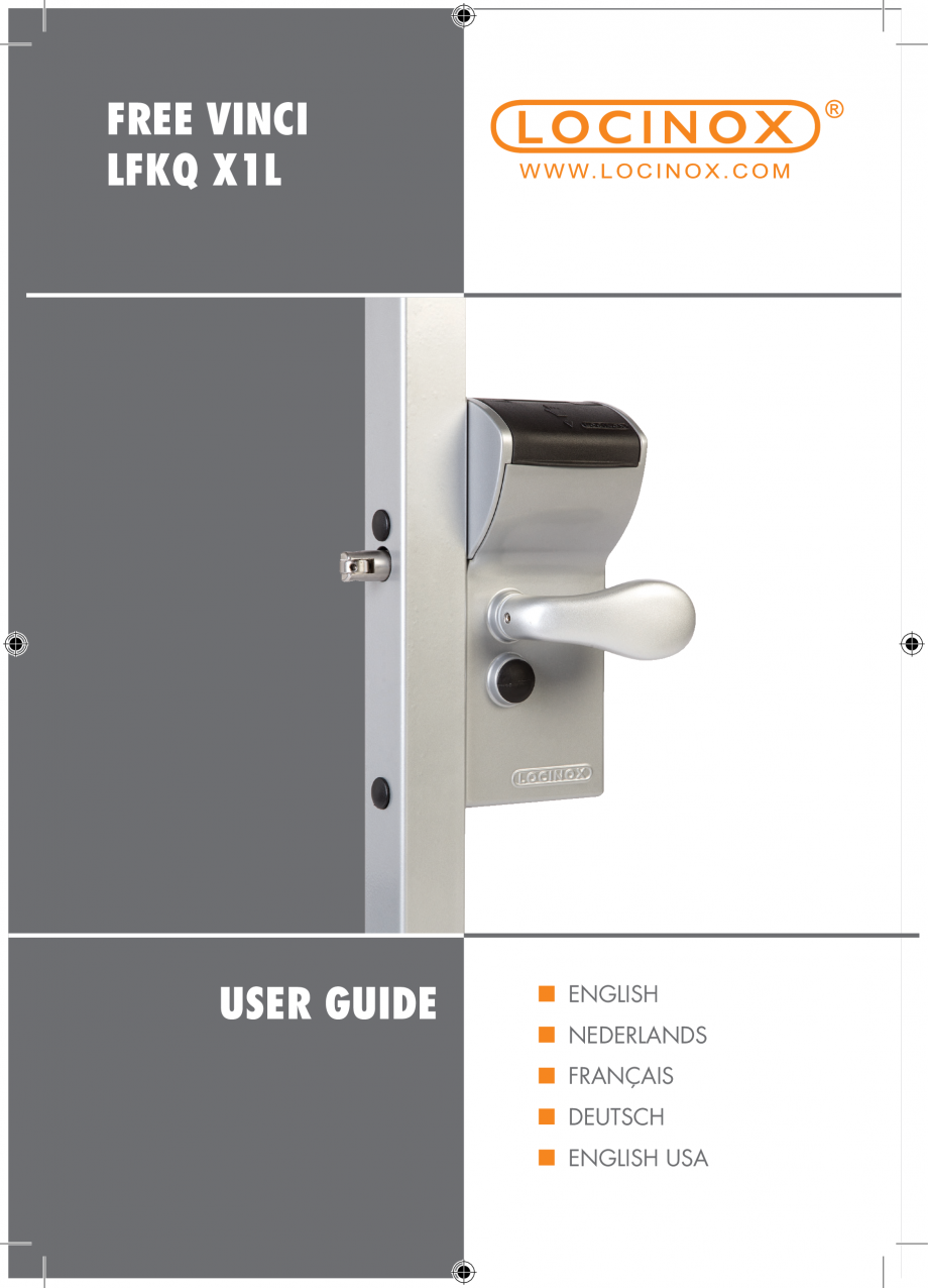
Incuietoare cu cifru pentru porti pietonale - FREE VINCI LOCINOX LFKQ X1
Limba: Engleza, Olandeza, Germana, Franceza
Tip documentatie: Instructiuni montaj, utilizare
Salvează pdf
Full screen
FREE VINCI
LFKQ X1L
USER GUIDE
ENGLISH
NEDERLANDS
FRANÇAIS
DEUTSCH
ENGLISH USA
• As manufacturer of this product, we guarantee that we have
taken all the necessary steps in order for this product to comply
with the current safety requirements.
Copyright
Copyright © 2014 Locinox. All rights reserved.
This product incorporates copyright protected technology that is protected by a number of EU
patent method claims and other intellectual property rights owned by the Locinox Corporation
and other rightholders.
Use of this copyright protected technology must be authorized by the Locinox Corporation.
Reverse engineering or disassembly is prohibited. No part of this publication can either
be reproduced, communicated, transcribed, stored in a retrieval system or be translated
into any language in any form or by any means, whether electronic, mechanical, magnetic,
optical, chemical, manual or otherwise, unless explicit written consent has been given by the
copyright holder.
Not
ice
The contents of this publication is subject to change. The company reserves the right to alter the
contents of this publication at any time and without notice. The contents of this publication may
contain inaccuracies or typographical errors and is supplied for informational use only.
Technical Support
If you require any additional information or assistance during the installation, please contact your
dealer, who will be able to provide the latest information. Alternatively, you can visit the Locinox
website for more technical information or e-mail us on locinox@locinox.com
Index
1. Introduction
2. Package contents
3. Components
4. Specifications
5. Profile preparation
6. Changing the codepanel to the
entrance side
7. Code setting
8. Mounting the handles
9. Turn the rollerbolt to match the closing
direction
10. Operation
11. Mounting the Vinci
ENGLISH
Manual - English
Manual - Nederlands
8. Installatie van de hendels
9. Draai de rolltop in de sluitrichting
10. Inhoud
11
. Montage van de Free Vinci
NEDERLANDS
1. Introductie
2. Inhoud
3. Onderdelen
4. Specificaties
5. Voorbereiding van profielen
6. Codepaneel verplaatsen naar de
toegangszijde
7. Instellen van de code
1. Introduction
2. Contenu de l’emballage
3. Composants
4. Spécifications
5. Préparation du profil
6. Modification du code sur le côté
d’entrée
7. Programmation du code
8. Montage des poignées
9. Tourner le pêne à roulette pour correspondre
avec le sens d’ouverture de la porte
10. Opération
11. Montage du Free Vinci
FRANçAIS
Manuel - Français
8. Montage der Drücker
9. Drehen Sie den Rollriegel der Schliessrichtung
entsprechend
10. Operation
11. Montage des Free Vinci Schlosses
Manual - English USA
6. Changing the codepanel to the
entrance side
7. Code setting
8. Mounting the handles
9. Turn the rollerbolt to match the closing
direction
10. Funktion
11. Mounting the Vinci
1. Introduction
2. Package contents
3. Components
4. Specifications
5. Profile pr
eparation
3
ENGLISH USA
1. Einleitung
2. Inhalt
3. Unterteile
4. Spezifikationen
5. Vorbereitung der Profile
6. Tastatur an der Eingangsseite installieren
7. Code einstellen
DEUTCH
Betriebsanleitung - Deutsch
ENGLISH
Manual - English
1. Introduction
Thank you for choosing a Locinox mechanical code lock with free exit! Please read the following
instructions thoroughly before mounting the Free Vinci. Enclosed you will find all relevant user
information concerning the Free Vinci.
2. Package contents
Please check if your package contains the following items:
2
1
3
4
5
Please contact your supplier should any of the above items be damaged or missing.
1
2
3
4
5
4
Mechanical code lock with free exit for swing gates
3006C/2 (Aluminium half club) & 3006R/2 (Aluminium half knob)
Extra code screws (2x)
Cover caps (2x)
Allen key (3mm) (1x)
The drawing below shows the names of the most important components. This drawing can be used
as reference throughout the manual.
A
H
Self-l
atching bolt (D)
Distance spacer
H
Hexagon socket head screw
Closing cover
J
D
Half handle 3006R/2
I
E
Half handle 3006C/2
G
F
Reset button
F
B
C
E
I
Code panel
D
A
Rain and dust cover
B
J
C
Cover screw
G
4. Specifications
• The Free Vinci is a 100% mechanical code lock, which does not need a battery nor
electricity to function.
• The code lock is equipped with a single-side operational code panel. This enables you to
work with an entrance code and a quick free-exit handle.
• At the entrance side, the handle can be deblocked by means of the code panel. Upon entering
the correct code, the handle is released and you can retract the self-latching bolt by means of
the handle.
• The code panel is protected by a polyamide cover. This prevents dust and rain to
penetrate.
• The quality code lock was designed in a very user-friendly manner. Changing the code setting
is very easy. A 4 to 6-digit entrance code can be set by means of the code scr
ews.
• The lock is equipped with a security press plate which rules out detection of the secret code
by putting pressure on the handle. After the correct code has been entered and the handle has
been pushed down, the code is automatically reset.
Gap adjustment
± 20 mm
Left/Right hand changing
180°
5
ENGLISH
3. Components
Determine the correct position of the lock in the gate frame. The mounting holes can be prepared
by means of the drawing below.
NOTE! The hole of the self-latching bolt, needs to be larger (Ø24 mm) at the back of the gate
frame then at the front (Ø18 mm). This allows you to fit the Free Vinci easily into the gate frame
when a minimum distance (110 mm) between the gate frame and the first gate bar is used.
95
102
2x Ø9
Ø24
20
2x Ø15
Ø18
140
120
218
ENGLISH
5. Profile preparation
31
M IN
. 110
6. Switching the codepanel to the entrance side
Before mounting the Free Vinci to the gate, check if the code entry side is at the correct side
of the
gate. If not, follow the instructions below to change the codepanel to the entrance side of the gate.
Step 1: Remove the closing cover.
First remove the cover screw and then slide out the closing cover and the dust- & raincover.
6
Slide out the code panel. Loosen the code mechanism screw and flip the code mechanism to the
other side.
Step 3: Remount the code panel
Tighten the code mechanism screw. Change the personal code following the instructions in Chapter 7, Code setting. When the numeric plate is in the correct position, you are ready to replace
the code panel. CAUTION! The reset button always needs to be on the latch bolt side of the lock.
Step 4: Reinstall the covers
After inserting the code panel, insert the Dust and Rain Cover so the lid opens over the code panel.
Slide the Closing Cover into position and tighten the screw. CAUTION! We recommend you to test
the lock (see chapter 10 Operation) before mounting the lock.
7
ENGLISH
Step 2: Switch the code mech
anism to the other side
ENGLISH
7. Code setting
Because of safety reasons, the Free Vinci is developed in such a manner that the code
can only be changed when it is not mounted. The default setting of the code is 1-2-3-4.
The steps below explain how you can modify your own personal code in a fast and simple manner.
The Free Vinci enables the setting of a 4 to 6-digit code.
Step 1: Remove the code panel.
After removing the code panel, you will find the red and green code screws. When dealing with
a new lock, the green screws are set in position 1-2-3-4, as shown. Remove all code screws from
the code mechanism with the enclosed Allen key.
Step 2: Set your personal code
Insert the green code screws in the position you want your personal code to be. Fill the remaining
holes with the red screws. All holes must be filled with a screw. Tighten the screws down so they
are firmly seated.
8
NOTE! The handle at the top position is the code entrance handle of the gate. The bottom position
is for the free exit handle on the “safe” side of the gate.
CAUTION! Install the handle shaft so that the handle’s set screw tightens into the spreader side
of the shaft.
9. Turn the rollerbolt to match the closing direction
CAUTION! Before mounting the Free Vinci to the gate, control if the rollerbolt is in the correct
position. If not, remove the screws and turn the rollerbolt.
NOTE! We recommend to use a threadlocker for the rollerbolt mounting screws. Tighten the
screws securly.
180°
9
ENGLISH
8. Mounting the handles
ENGLISH
10. Operation
Test the reset function: (Drawing A) After having entered an incorrect code, the handle
should remain blocked. (Drawing B) Now press the reset button and enter the correct code.
(Drawing C & D). The handle can be pushed down, this will retract the lock’s self-latching bolt.
(Drawing E). After using the handle, the code is automatically reset.
A
B
C
D
E
11. Mounting the Free Vinci
After testing the operation of your lock, th
e Free Vinci can be mounted onto the gate. The fast, easy
and typical Locinox mounting is explained below. First slide the spacer tubes over the hexagon
socket head screws and fix the lock onto the gate profile by using the hex key. 1 & 2 . Tighten
the hexagon socket head screws and cover the holes with the enclosed plastic cover caps. 3
1
10
2
3
Handleiding - Nederlands
1. Introductie
Bedankt voor het kiezen van een Locinox mechanisch codeslot met vrije uitgang. Gelieve
voor installatie van de Free Vinci aandachtig de instructies te lezen. U vindt er alle relevante
gebruikersinformatie mbt de Free Vinci in terug.
2. Inhoud
NEDERLANDS
Gelieve te controleren of de verpakking volgende onderdelen bevat:
2
1
3
4
5
Contacteer uw verdeler mocht één van bovenstaande onderdelen ontbreken of beschadigd zijn.
1
2
3
4
5
Mechanisch codeslot voor draaipoorten met vrije uitgang
3006C/2 (Halve aluminium kruk) & 3006R/2 (Halve aluminium bolkruk)
Extra code schroeven (2x)
Afdekdopjes
(2x)
Inbussleutel
11
3. Onderdelen
De onderstaande tekening vermeldt de namen van de belangrijkste onderdelen. Deze tekening
kan als referentie gebruikt worden doorheen de handleiding.
A
NEDERLANDS
H
Dagpen
Afstandsbus
H
Zeskant inbus schroef
Afdekkap
J
D
Halve bolkruk 3006R/2
I
E
Halve kruk 3006C/2
G
F
Reset knop
F
B
C
E
I
Codepaneel
D
A
Afdekkap tegen regen en stof
B
J
C
Schroef voor afdekkap
G
4. Specificaties
• De Free Vinci is een 100% mechanisch codeslot. Er is geen batterij of elektriciteit nodig om te
functioneren.
• Het codeslot is uitgerust met een éénzijdig codepaneel. Hierdoor kunt u werken met één
beveiligde zijde en een snelle, vrije uitgang met bolkruk.
• Aan de toegangszijde wordt de hendel geblokkeerd door een codepaneel. Na
het intoetsen van de code kunt u de dagpen terugtrekken door bediening van de
hendel.
• Het codepaneel is beschermd door een polyamide cover. Dit beschermt het mechanisme tegen
indringing van
vuil en regen.
• Het hoogwaardige codeslot is zeer gebruiksvriendelijk. U kan eenvoudig de code wijzigen.
Een 4 tot 6-cijferige code kan ingesteld worden met behulp van de codeschroeven.
• Het slot is uitgerust met een veiligheidsdrukplaat die codedetectie door druk te zetten op de
hendel, uitsluit. Na het ingeven van de correcte code en het openen van de poort wordt de code
automatisch gereset.
Bijregelen dagpen
± 20 mm
12
Links/rechts omstelling
180°
5. Voorbereiding van profielen
Bepaal de juiste positie van het slot in het poortframe. De gaten kunnen voorbereid worden met
behulp van onderstaande tekening.
OPGEPAST! Het gat voor de dagpen is groter (Ø24 mm) aan de achterzijde van het profiel dan
aan de voorzijde (Ø18 mm). Hierdoor kunt u de Free Vinci eenvoudig monteren bij de minimum
afstand (110 mm) tussen het poortprofiel en de eerste poortspijler.
102
NEDERLANDS
95
2x Ø9
Ø24
140
120
218
20
2x Ø15
Ø18
31
M IN
. 110
6. Codepaneel verplaatsen
naar de toegangszijde
Controleer voor installatie of de zijde met het codepaneel aan de correcte kant zit. Indien niet,
volg onderstaande instructies op.
Stap 1: Verwijder het afdekkapje.
Draai eerst de schroef van de cover los en schuif dan de afdekkap en stof- en regenkap los.
13
Stap 2: Verwisselen van het codepaneel naar de andere zijde
Schuif het codepaneel uit. Los de schroef van het codemechanisme en verschuif het codepaneel
naar de andere zijde.
NEDERLANDS
Stap 3: Opnieuw plaatsen van het codepaneel
Schroef het codemechanisme opnieuw vast. Zie hoofdstuk 7 (code instellen) als u uw persoonlijke
code wenst in te stellen. Na het in de juiste positie plaasten van het numerieke bord bent u klaar
om het codepaneel opnieuw te plaatsen. OPGEPAST! De reset knop moet altijd aan de zijde waar
de dagpen van het slot zit, gemonteerd worden.
Stap 4: Montage van de afdekkap
Na het bevestigen van het codepaneel kan men de afdekkappen plaatsen. Plaats de kap zo dat
het over het code
paneel zit. Schuif de afdekkap in positie en schroef vast. OPGEPAST! Het is
aangewezen het slot eerst te testen vooraleer u het monteert (zie hoofdstuk 10: Bediening)
14
7. Instellen van de code
Omwille van veiligheidsredenen is het Free Vinci codeslot zo ontworpen dat de code
enkel gewijzigd kan worden wanneer het slot niet gemonteerd is. De standaardcode is 1-2-3-4.
Onderstaand stappenplan legt uit hoe u uw persoonlijke code snel en eenvoudig kan instellen.
Na het verwijderen van het codepaneel worden de rode (stop) en groene (go) code schroeven
zichtbaar. De fabrieksinstelling van de groene schroeven is standaard 1-2-3-4, zoals getoond.
Verwijder alle codeschroeven van het codemechanisme met behulp van de bijgevoegde inbussleutel.
Stap 2: Instellen van de persoonlijke code
Plaats de groene codeschroeven in de gewenste positie (afhankelijk van uw gekozen code). Vul de
overgebleven gaten met de rode schroeven. Alle gaten moeten gevuld worden met een schroef.
Schroef ze vast zoda
t de gaten goed gedicht zijn.
15
NEDERLANDS
Stap 1: Verwijderen van afdekkap en codepaneel.
8. Installatie van de hendels
OPMERKING! De bovenste hendelpositie is voor de hendel aan de zijde van het code
mechanisme. De onderste hendelpositie is voor de hendel voor vrije uitgang.
OPGEPAST! Installeer de krukstift met de gesplitste kant naar buiten zodat de schroef erin
geschroefd kan worden.
NEDERLANDS
9. Draai de rolltop in de sluitrichting
OPGEPAST! Controleer voor u het Free Vinci codeslot installeert, of de rolltop in de correcte positie
staat. Zoniet, los de vijzen en draai de rolltop.
OPMERKING! We raden aan om een borgingslijm aan te brengen voor montage van de rolltop
schroeven. Span ze zorgvuldig aan.
180°
16
10. Bediening
NEDERLANDS
Druk een foutieve code in om de reset functie te testen. (Tekening A) Nadat u de foutieve code
ingevuld heeft, blijft de hendel geblokkeerd. (Tekening B) Duw nu de reset knop in en geef de juiste
code in. (Tekening C & D). De hendel k
an ingedrukt worden na het ingeven van de correcte code.
Dit trekt de dagpen terug. (Tekening E). Na het gebruiken van de hendel wordt de code automatisch
gereset. Hierdoor dient u steeds de code opnieuw in te drukken wanneer u de poort wenst te
openen.
A
B
C
D
E
11. Montage van de Free Vinci
Na het testen kunt u de Free Vinci installeren. De snelle, eenvoudige en typische Locinox montage
wordt uitgelegd in onderstaande tekeningen. Schuif om te beginnen de afstandsbussen over de
zeskant inbus schroeven en zet het slot vast op het poortprofiel met behulp van de inbussleutel.
1 & 2 . Span de zeskant inbus schroeven aan en bedek de gaten met de bijgeleverde plastic
afdekdopjes. 3
1
2
3
17
Manuel - Français
1. Introduction
Merci d’avoir choisi une serrure à codes mécanique Locinox avec sortie Libre! S’il vous plait
veuillez lire attentivement les instructions avant de monter la serrure FREE VINCI. Vous trouverez
dans ce document toutes les informations sur cette serrure
FREE VINCI.
2. Contenu de l’emballage
S’il vous plait veuillez vérifier que votre colis contient les élements suivants:
2
FRANçAIS
1
3
4
5
S’il vous plaît veuillez contacter votre fournisseur si l’un des éléments ci-dessous est endommagé
ou manquant.
1
2
3
4
5
18
Serrure à codes mécanique avec sortie libre pour portail battant
3006C/2 (Demie poignée Club en aluminium) & 3006R/2 (Demi bouton en aluminium)
Vis code, verte (2x)
Bouchons
Clé allen (3mm) (1X)
3. Composants
Le dessin ci-dessous désigne le nom des éléments les plus importants. Ce dessin peut être utilisé
comme référence dans le manuel.
Couvercle anti pluie et anti
poussière
B
Bloc clavier
Touch Reset
D
Demi poignée Club 3006C/2
E
Demi poignée Bouton 3006R/2
F
Pêne demi-tour
G
Entretoise
H
Vis BTR
I
A
I
B
F
E
D
H
Couvercle de fermeture
G
J
Vis du couvercle
4. Spécifications
• La FREE VINCI est une serrure à code 100% mécanique, fonctionnement sans batteri
e ni
électricité.
• La serrure à codes est équipé d’un seul bloc clavier pour un côté. Cela vous permet de
travailler avec un code d’entrée et une sortie libre rapide.
• Au niveau du côté entrée, la poignée est bloquée grâce au bloc clavier. En entrant le code
correct, la poignée est déverrouillé et vous pouvez retracter le pêne demi-tour.
• Le bloc clavier est protégé par un couvercle en polyamide. Cela empêche la poussière et la
pluie de pénétrer.
• La serrure à code a été conçue pour une utilisation ergonomique. La modification du code est très
facile à réaliser. Un code d’entrée de 4 à 6 chiffres peut être programmé au moyen des vis de
code supplémentaire.
• La serrure est équipé d’une plaque de sécurité qui exclut la détection du code secret en faisant
pression sur la poignée. Après la saisie du bon code et l’utilisation de la poignée, le code est
automatiquement réinitialisé.
Réglage du pên
e
± 20 mm
Réversible gauche / droite
180°
19
FRANçAIS
A
C
J
C
5. Préparation du profil
Déterminez la position de la serrure sur le cadre de la porte. Les trous peuvent être préparés en
utilisant le schéma suivant. ATTENTION! Le trou pour le pêne demi-tour est plus grand (Ø24 mm)
sur la partie intérieur du profil que du côté extérieur (Ø 18 mm). Cela vous permet de monter plus
facilement la FREE VINCI, la distance minimale entre le profil et le premier barreau de la porte
doit être de 110mm.
95
102
2x Ø9
Ø24
140
FRANçAIS
120
218
20
2x Ø15
Ø18
31
M IN
. 110
6. Modification du code sur le côté d’entrée
Avant de monter la FREE VINCI sur la porte, vérifier si le côté d’entrée à codes est sur le bon côté
de la porte. Sinon, suivez les instructions ci-dessous pour changer de sens le bloc clavier.
Etape 1: Retirer le couvercle de fermeture
Commencez par retirer la vis du couvercle puis faites glisser le couvercle de fermeture et le
c
ouvercle anti-pluie et anti-poussière
20
Etape 2: Mettez le mécanisme de code de l’autre côté
Faites glisser le bloc clavier. Desserrer la vis du mécanisme du code et retourner le mécanisme de
code de l’autre côté.
Etape 3: Remonter le bloc clavier
FRANçAIS
Serrer la vis du mécanisme du code. Modifiez le code personnel en suivant les instructions du
chapitre 7. Avec la plaque numérique dans la position correcte, vous êtes prêt à positionner le
bloc clavier. ATTENTION! Le bouton de remise à zéro a toujours besoin d’être sur le côté de la
têtière de la serrure.
Etape 4: Remettez les couvercles
Après avoir inséré le bloc clavier, insérez le couvercle anti poussière et anti pluie de sorte que le
couvercle puisse s’ouvrir sur le bloc clavier. Faites glisser le couvercle de fermeture en position et
serrer la vis. ATTENTION! Nous vous recommandons de tester la fonction de verrouillage (voir
chapitre 10 Fonctionnement) avant le montage de la serrure.
2
1
7. Programmation du code
Pour des raisons de sécurité, la FREE VINCI est développé de telle sorte que le code ne peut être
modifié que si la serrure n’est pas monté sur une porte. Le réglage par défaut du code est 1-23-4. Les étapes suivantes expliquent comment vous pouvez modifier votre code personnel d’une
manière simple et rapide. La FREE VINCI permet la création d’un code de 4 à 6 chiffres.
Etape 1: Retirez le couvercle de fermeture et le bloc clavier
Après avoir retiré le bloc clavier, vous trouverez des vis rouge (non-code) et des vis vertes (code) .
A la sortie de l’usine, les vis codes vertes sont automatiquement positionné sur le 1-2-3-4, comme
indiqué. Retirez toutes les vis du mécanisme de code avec la clé Allen fournie.
FRANçAIS
Etape 2: Définir votre code personnel
Insérez les vis code vertes dans les positions que vous voulez pour faire votre code personnel.
Complétez les trous restants avec les vis rouges. Tous les trous doivent êtr
e remplis avec une vis.
Serrer les vis en bas afin qu’elles soient bien en place.
22
8. Montage des poignées
REMARQUE! La poignée en position haute est la poignée d’entrée du code sur le côté avec
contrôle d’accès. La position basse est pour la poignée de sortie libre. ATTENTION! Installez le
carré avec le côté fendu de telle sorte que la vis de fixation de la poignée peut être vissé.
ATTENTION! Avant de monter la FREE VINCI sur la porte, vérifiez si le pêne à roulette est dans la
bonne position par rapport au sens d’ouverture. Sinon, enlever les vis et tourner pêne à roulette.
NOTE! Nous vous recommandons le Loctite BLEU frein filet pour les vis de montage du pêne à
roulette. Serrer les vis en toute sécurité.
180°
23
FRANçAIS
9. Tourner le pêne à roulette pour correspondre avec le sens d’ouverture de la porte
10. Operation
Entrez un faux code afin de tester la fonction de réinitialisation. (Dessin A) Après avoir entré
un code incorre
ct, la poignée reste bloquée. (Dessin B) Maintenant appuyez sur le bouton de
réinitialisation et entrez le code correct. (Dessin C & D). TLa poignée peut être manoeuvrée
après avoir entré le code correct. Celà rétracte le pêne demi-tour de la serrure. (Dessin E). Après
l’utilisation de la poignée, le code est automatiquement remis à zéro. Pour ce faire, le code doit
être entré lors de chaque utilisation afin de pouvoir ouvrir la FREE VINCI.
A
B
C
FRANçAIS
D
E
11. Montage de Free Vinci
Après avoir testé le fonctionnement de votre serrure, la FREE VINCI peut être monté sur la porte.
Le montage facile typique Locinox est présenté ci-dessous. Première glisser les entretoises sur les
BTR et monter la serrure sur le profil de la porte à l’aide de la clé hexagonale. 1 & 2 . Serrer
les vis BTR et couvrir les trous avec les capuchons en plastique prévus. 3
1
24
2
3
Betriebsanleitung - Deutsch
1. Einleitung
Danke, dass Sie sich für ein Locinox mechani
sches Codeschloss mit freiem Ausgang entschieden
haben. Lesen Sie sorgfältig die Instruktionen, bevor Sie das Free Vinci Schloss installieren. Darin
finden Sie alle relevante Gebrauchsinformation bezüglich des Free Vinci Schlosses.
2. Inhalt
Kontrollieren Sie, ob die Verpackung folgende Unterteile enthält:
2
1
3
4
5
Kontaktieren Sie Ihren Verteiler falls eines der obenstehenden Unterteile fehlt oder beschädigt ist.
Mechanisches Codeschloss für Drehtore mit freiem Ausgang
3006C/2 (Aluminium Halbdrücker Club)
DEUTCH
1
2
3
4
5
Codeschrauben, grün (2x)
Abdeckkappen (2x)
Inbusschlüssel (3mm) (1x)
25
3. Unterteile
Untenstehende Zeichnung erwähnt die Bezeichnungen der wichtigsten Unterteile. Diese Zeichnung
dient als Referenz für die ganze Betriebsanleitung.
A
H
Falle
Distanzhülse
H
Sechskant Inbusschraube
Abdeckkappe
J
D
Halbdrücker 3006R/2
I
E
Halbdrücker 3006C/2
G
F
Reset Knopf
F
B
C
E
I
Tastatur
D
A
Schutzkappe gegen Regen und Staub
B
J
C
Schraube für Abdeckkappe
G
4. Spezifikationen
DEUTCH
• Das Free Vinci Schloss ist ein 100 % mechanisches Codeschloss, das ohne Strom oder Batterie
funktioniert.
• Das Codeschloss hat ein einseitiges Tastatur. So ist eine Seite mit Code gesichert und bietet die
andere Seite schnellen und freien Ausgang mit dem runden Halbdrücker.
• An der Eingangsseite wird der Drücker beidem Tastatur blockiert. Wenn Sie den Code
eintasten, können Sie die Falle mit dem Drücker zurückziehen.
• Das Tastatur ist mittels einer Polyamid Abdeckkappe geschützt. So wird der Mechanismus
gegen das Eindringen von Staub und Regen geschützt.
• Das hochwertige Codeschloss ist sehr benutzerfreundlich. Sie können den Code ganz
einfach abändern. Mit den Codeschrauben können Sie einen Code von 4 bis 6 Ziffern einstellen.
• Eine innere Drückplatte verhindert Codedetektion. Man kann den Code nicht detektieren wenn
man den Drücker betätigt. Nachdem Sie den richtigen Code eing
etastet haben und das Tor mit
dem Drücker geöffnet haben, wird der Code automatisch gereset.
Einstellen der Falle
± 20 mm
26
Links/Rechts Einstellen
180°
5. Vorbereitung der Profile
Bestimmen Sie die richtige Position des Schlosses im Torrahmen. Die Löcher können anhand untenstehender Zeichung vorbereitet werden. ACHTUNG ! Das Loch für die Falle ist grösser (Ø24
mm) an der Hinterseite des Profils als an der Vorderseite (Ø18 mm). Dadurch können Sie das
Free Vinci Schloss einfach montieren, auch bei einer minimalen Distanz (110 mm) zwischen dem
Torprofil und dem ersten Torstab.
95
102
2x Ø9
Ø24
140
120
218
20
2x Ø15
Ø18
31
M IN
. 110
6. Tastatur an der Eingangsseite installieren
Schritt 1: Entfernen Sie die Abdeckkappe.
Lockern Sie erst die Schraube der Abdeckkappe und schieben Sie dann die Abdeckkappe und
die Schutzkappe raus.
27
DEUTCH
Bevor Sie das Schloss installieren, kontrollieren Sie ob das Tastatur an der richtigen Seite sitzt.
Wenn nicht, f
olgen Sie dann untenstehenden Instruktionen.
Schritt 2: Wechseln Sie das Codepult zur anderen Seite
Schieben Sie das Codepult raus. Lockern Sie die Schraube des Codemechanismus und verschieben Sie den Codemechanismus zur anderen Seite.
Schritt 3: Tastatur wieder montieren
Schrauben Sie den Codemechanismus wieder fest. Stellen Sie Ihren persönlichen Code ein und
folgen Sie dabei die Instruktionen laut Kapitel 7 (Code einstellen). Nachdem Sie das numerische
Schild in der richtigen Position gedreht haben, können Sie das Tastatur neu installieren. ACHTUNG
! Der Reset Knopf soll immer an der Seite wo die Falle des Schlosses sich befindet montiert werden.
Schritt 4: Montage der Kappen
DEUTCH
Nachdem Sie das Tastatur reingeschoben haben, können Sie die Kappen wieder anbringen.
Schieben Sie die Schutzkappe so rein, dass die über das Tastatur geöffnet werden kann. Schieben
Sie dann die Abdeckkappe wieder rein und schrauben Sie diese fest. ACHTUNG! Es ist ratsam,
das Schloss zu teste
n (siehe Kapitel 10 Funktion), bevor Sie es montieren.
28
7. Code einstellen
Aus Sicherheitsgründen wurde das Free Vinci Schloss so entwickelt, dass Sie den Code nur
abändern können, wenn das Schloss nicht montiert ist. Der Standardcode ist 1-2-3-4.
Untenstehende Schritte erklären, wie Sie schnell und einfach Ihren eigenen Code von 4 bis 6
Ziffern einstellen können.
Schritt 1: Entfernen Sie die Abdeckkappe und das Codepult.
Nachdem Sie das Codepult entfernt haben, sehen Sie die roten (stop) und grünen (go) Codeschrauben. Die Standardeinstellung der grünen Schrauben ist 1-2-3-4, wie gezeigt. Entfernen Sie
alle Schrauben vom Codemechanismus mit dem mitgelieferten Inbusschlüssel.
Schritt 2: Einstellen Ihres persönlichen Codes
DEUTCH
Legen Sie die grünen Codeschrauben in der gewünschten Position (abhängig des von Ihnen
gewählten Codes). Füllen Sie die übriggebliebenen Löcher mit den roten Schrauben. Alle Löcher
müssen mit einer Schraube versehen werden. Schrauben Si
e die Codeschrauben gut fest.
29
8. Montage der Drücker
BEMERKUNG! Die obere Drückerposition ist für den Drücker der mit Code gesicherten Seite des
Tores. Die untere Position ist für den Drücker der offenen Seite des Tores. ACHTUNG! Installieren
Sie den Drückerstift mit der gesplitteten Seite nach aussen, so dass die Schraube des Drückers
reingeschraubt werden kann.
9. Drehen Sie den Rollriegel der Schliessrichtung entsprechend
ACHTUNG! Kontrollieren Sie ob der Rollriegel in der richtigen Position steht, bevor Sie das Free
Vinci Schloss installieren. Wenn das nicht der Fall ist, lockern Sie die Schrauben und drehen
Sie den Rollriegel. BEMERKUNG! Wir empfehlen Sicherungsmittel für die Montage der Rollriegelschrauben. Spannen Sie die sorgfältig an.
DEUTCH
180°
30
10. Funktion
Tasten Sie einen falschen Code ein um die Reset Funktion zu testen. (Abbildung A) Nachdem Sie
einen falschen Code eingetastet haben, bleibt der Drücker blockiert. (Abbildung B) Drücken Sie
jetz
t den Reset Knopf ein und tasten Sie den richtigen Code ein. (Abbildung C & D). Wenn Sie
den richtigen Code eingetastet haben, können Sie den Drücker nach unten drücken. So wird die
Falle zurückgezogen. (Abbildung E). Nach Betätigung des Drückers wird der Code automatisch
gereset. Dadurch ist man immer verpflichtet den Code neu einzutasten, wenn man das Tor öffnen
möchte.
A
B
C
D
E
Nachdem Sie die Funktion des Schlosses getestet haben, können Sie das Free Vinci Schloss installieren. Die schnelle, einfache und typische Locinox Montage wird in untenstehenden Zeichnungen
erklärt. Schieben Sie als erstes die Distanzhülsen über die Sechskant Inbusschrauben und montieren Sie das Schloss am Torprofil mit dem Inbusschlüssel. 1 & 2 . Spannen Sie die Sechskant
Inbusschrauben an und bedecken Sie die Löcher mit den beigelieferten Plastik Abdeckkappen. 3
1
2
3
31
DEUTCH
11. Montage des Free Vinci Schlosses
Manual - English USA
1. Introduction
Thank you for choosing a L
ocinox mechanical code lock with free exit! Please read the following
instructions thoroughly before mounting the Free Vinci. Enclosed you will find all relevant user
information concerning the Free Vinci.
2. Package contents
Please check if your package contains the following items:
2
1
3
4
5
Please contact your supplier should any of the above items be damaged or missing.
1
2
3
4
5
ENGLISH USA
32
Mechanical code lock with free exit for swing gates
3006C/2 (Aluminium half club) & 3006R/2 (Aluminium half knob)
Extra code screws, green (2x)
Cover caps (2x)
Allen key (3mm) (1x)
3. Components
The drawing below shows the names of the most important components. This drawing can be used
as reference throughout the manual.
A
H
Self-latching bolt (D)
Spacer tube
H
Hex head socket screw
Closing cover
J
D
Half handle 3006R/2
I
E
Half handle 3006C/2
G
F
Reset button
F
B
C
E
I
Code panel
D
A
Rain and dust cover
B
J
C
Cover screw
G
4. Specifications
• The
Free Vinci is a 100% mechanical code lock, which does not need a battery nor
electricity to function.
• The code lock is equipped with a single-side operational code panel. This enables you to
work with an entrance code and a quick free-exit handle.
• At the entrance side, the handle is blocked by means of the code panel. Upon entering the
correct code, the handle is released and you can retract the self-latching bolt by means of the
handle.
• The code panel is protected by a polyamide cover. This prevents dust and rain from
penetrating.
• The quality code lock was designed in a very user-friendly manner. Changing the code setting
is very easy. A 4 to 6-digit entrance code can be set by means of the additional code screws.
• The lock is equipped with a security press plate which rules out detection of the secret code
by putting pressure on the handle. After the correct code has been entered and the gate has
been opened with the handle, the code is automat
ically reset.
± 3/4”
Left/Right hand changing
180°
33
ENGLISH USA
Gap adjustment
5. Profile preparation
Determine the correct position of the lock in the gate frame. The mounting holes can be prepared
by means of the drawing below.
NOTE! The hole of the self-latching bolt, needs to be larger (Ø 1”) at the back of the gate frame
then at the front (Ø3/4” mm). This allows you to fit the Free Vinci easily into the gate frame when
a minimum distance (4-3/8”) between the gate frame and the first gate bar is required.
3 -5 / 8
” 4”
2x Ø3/8”
Ø1”
2x Ø5/8”
5-9/16”
4-23/32”
8-9/16”
13/16”
Ø3/4”
1/4”
M IN 1 . 4-3
/8”
6. Changing the codepanel to the entrance side
Before mounting the Free Vinci to the gate, check if the code entry side is at the correct side of the
gate. If not, follow the instructions below to change the codepanel to the entrance side of the gate.
Step 1: Remove the closing cover.
First remove the cover screw and then slide
out the closing cover and the dust- & raincover.
ENGLISH USA
34
Step 2: Switch the code mechanism to the other side
Slide out the code panel. Loosen the code mechanism screw and flip the code mechanism to the
other side.
Step 3: Remount the code panel
Tighten the code mechanism screw. Change the personal code following the instructions in Chapter 7, Code setting. With the numeric plate in the correct position, you are ready to replace the
code panel. CAUTION! The reset button always needs to be on the latch bolt side of the lock.
Step 4: Reinstall the covers
35
ENGLISH USA
After inserting the code panel, insert the Dust and Rain Cover so the cover opens over the code
panel. Slide the Closing Cover into position and tighten the screw. CAUTION! We recommend
you test the lock function (see chapter 10 Operation) before mounting the lock.
7. Code setting
Because of security reasons, the Free Vinci is developed in such a manner that the code
can only be changed when it is not
mounted. The default setting of the code is 1-2-3-4.
The steps below explain how you can modify your own personal code in a fast and simple manner.
The Free Vinci enables the setting of a 4 to 6-digit code.
Step 1: Remove the closing cover and code panel.
After removing the code panel, you will find the red (stop) and green (go) code screws. From the
factory, the green screws are automatically set in position 1-2-3-4, as shown. Remove all code
screws from the code mechanism with the enclosed Allen key.
Step 2: Set your personal code
Insert the green code screws in the position you want your personal code to be. Fill the remaining
holes with the red screws. All holes must be filled with a screw. Tighten the screws down so they
are firmly seated.
ENGLISH USA
36
8. Mounting the handles
NOTE! The handle at the top position is the code entrance handle on the secure side of the gate.
The bottom position is for the free exit handle on the “safe” side of the gate.
CAUTION! Install
the handle shaft so that the handle’s set screw tightens into the spreader side
of the shaft.
9. Turn the rollerbolt to match the closing direction
CAUTION! Before mounting the Free Vinci to the gate, check if the rollerbolt is in the correct
position. If not, remove the screws and turn the rollerbolt.
NOTE! We recommend threadlocker for the rollerbolt mounting screws. Tighten the screws
securly.
37
ENGLISH USA
180°
10. Operation
Enter a false code in order to test the reset function. Drawing A After having entered an incorrect
code, the handle remains blocked. Drawing B Now press the reset button and enter the correct
code. Drawing C & D. The handle can be moved after entering the correct code. This will retract
the lock’s self-latching bolt. Drawing E. After using the handle, the code is automatically reset. In
doing so, the code needs to be entered each time in order to open the Free Vinci.
A
B
C
D
E
11. Mounting the Free Vinci
After testing the operation of your lo
ck, the Free Vinci can be mounted onto the gate. The fast, easy
and typical Locinox mounting is explained below. First slide the spacer tubes over the hex head
socket screws and mount the lock onto the gate profile by using the hex key. 1 & 2 . Tighten
the hex head socket screws and cover the holes with the enclosed plastic cover caps. 3
ENGLISH USA
1
38
2
3
39
ENGLISH USA
Memo
*
M
A
N
U
-
0
0
0
1
9
9
*
2014-02-26 - rev 1
Copyright © 2014 Locinox. All rights reserved.
All specifications and figures are subject to change without notice.
Locinox nv - Mannebeekstraat 21 - B-8790 - Waregem - Belgium
Tel. +32 (0)56 77 27 66 - Fax. +32 (0)56 77 69 26
E-mail: locinox@locinox.com - Web: www.locinox.com
Alte documentatii ale aceleasi game
Instructiuni montaj, utilizare 2 p | EN - FR + inca 2 limbi
Instructiuni montaj, utilizare 40 p | EN - GE + inca 2 limbi