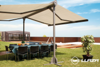
Copertina dubla cu ax comun si structura proprie LLAZA Duox
DUOX awning
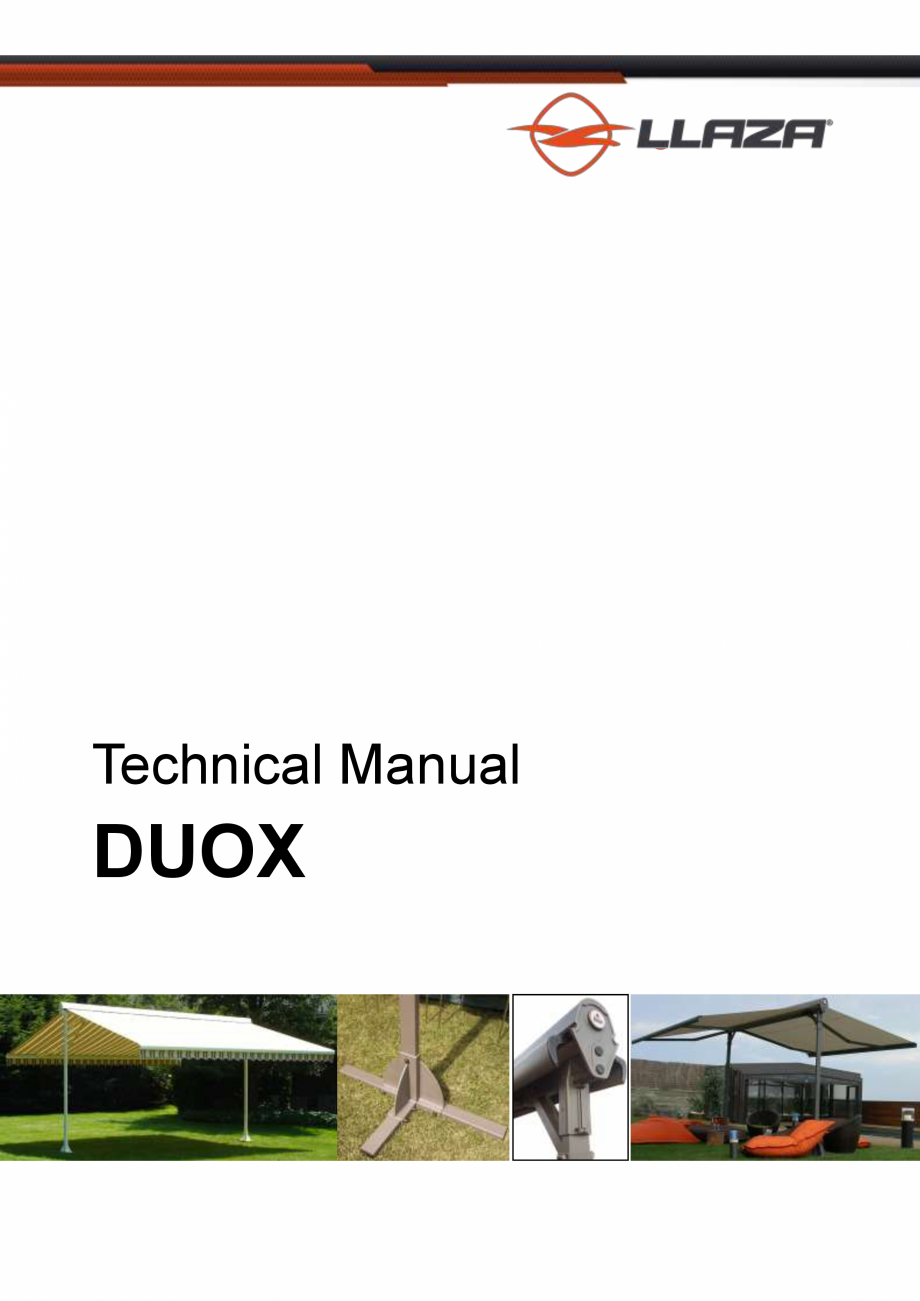
Technical Manual
DUOX
Page 1 - Copyright Llaza, S.A. - May 2012
DUOX awning
Page 2 - Copyright Llaza, S.A. - May 2012
DUOX awning
Contents
Descriptive specifications
5-8
Cutting, selection, and classification tables
9
Annotated cross-sectional diagrams
10
Instructions for cutting the fabric
11
Assembly instructions
12-16
Examples of installations
17-19
Page 3 - Copyright Llaza, S.A. - May 2012
DUOX awning
Page 4 - Copyright Llaza, S.A. - May 2012
DUOX awning
Descriptive specifications
1. GENERAL CHARACTERISTICS
The DUOX double awning brings together a variety of characteristics that make it ideal for use in areas where there are
no walls, ceilings, or other surfaces available to support it.
This need usually arises when a customer would like to install a sun protection system in an area free of any buildings
(gardens, terraces, parks, paved areas, etc).
The system consists of a structure that sustains an articulated sun protection assembly, which e
xtends to both sides in
unison.
The fabric that serves as the screening element is rolled onto a single tube.
The system consists of a unique self-bearing component, with three distinct suspension systems.
2. DESCRIPTION OF THE SYSTEM
The “DUOX” system is based on the conjunction and adaptation of a set of profiles, assembly pieces, articulated arms
with internal elongation springs, and the options available for generating rotational movement (gearbox or motor). All of
these components, together with acrylic or high-tech fabric, are required for the installation and operation of the system.
This product has been designed considering the requirements and demands it will subjected to while being used for its
intended purpose.
In order to create a product that will best meet the needs of the most customers, two intrinsic requirements must be taken into account when designing a system like this:
Dimensions
Exposure to the elements (sun, wind, rain)
These needs must take pre
cedence when choosing a system.
The relationship between these factors, and the need to compete with other awning models, means the materials chosen
in the manufacture of this product have taken on vital importance.
The set of profiles which hold up the support components of the sun protection system are made of treated, cold-formed
steel, with a lacquer finish.
The components of the structure that holds the sun protection system itself are made of lacquer-finished aluminium.
The bases for the support posts and the rest of the pieces that make up the structure and the system are also made from
lacquered aluminium.
Other materials have been selected for pieces that have a purpose other than for structure and support, such as the decorative caps and covers for the profiles, etc. High-tech plastics have been chosen for these components, which feature
levels of strength and technical inalterability that exceed the values required by current applicable standards.
Page 5 - Copyright Llaza,
S.A. - May 2012
DUOX awning
Descriptive specifications
3. DESCRIPTION OF THE PARTS THAT MAKE UP THE DUOX AWNING
Cold-formed steel has been selected for the posts in the support structure. These
are quadrangular bars measuring 80x40x2 millimetres.
The crossbar located on the top, which has the cassette support side brackets attached to its ends, is positioned in a distinctive manner (see drawing).
This system achieves the best results in terms of resistance to traction and sagging.
The joining piece for these components is made of aluminium and positioned like a T
joint, with both profiles then drilled all the way through to allow pass-through bolts to
keep this connection completely immobile despite any forces acting directly upon the system.
There are three options for the bases that sustain the structure, which are manufactured in aluminium by the casting or
gravity system:
Square base bolted to the ground:
Base set into the ground:
Page 6 - Copyright Llaza, S.A. - May 2012
DU
OX awning
Descriptive specifications
On-the-surface base for an independent structure:
The use of this last type of base requires the complementary use of two tubes as extensions, made with the
same materials and dimensions as those used for the
structure, in order to obtain a base that is a total of 2
metres long in the direction perpendicular to the awning,
and 6 metres long in the parallel direction. A 110-kg
counterweight must be placed on each of these extensions, with a total of 4 of these units per awning (weight
calculated based on the maximum admissible measurements for the DUOX model awning).
The acrylic or high-tech fabric offers superior sun protection, and extends and retracts by rolling on a steel tube.
This tube is anchored on two side brackets that attach to the ends of the upper horizontal support tube for the structure.
It is attached using an internal clamp that prevents the need to drill into the profile.
The rotational motion applied to the rolling tube when exten
ding or retracting the fabric is activated by means of a gearbox with a 1:5 ratio, which is accompanied by a tubular compensation spring. Motion is applied by either a manual crank
or an electric motor located inside one end of the rolling tube.
The other end of the rolling tube turns on a ball-bearing system that ensures technically calculated support so the system
operates smoothly and perfectly every time.
The extension of the fabric relies on structures attached to both sides, consisting of articulated ART-System arms and
the corresponding drop bar profiles.
The ART-System arms themselves consist of profiles with an internal tensioning system that uses an elongation mechanism, with transmission of the longitudinal difference by means of a patented flexible tape system. This ensures that the
product performs well above the applicable European EN 13561 standard.
When used properly, the ART-System arms will exceed 60,000 operational cycles. Also, the appropriate angular calculations f
or their components prevent them from rubbing against the fabric during the entire extension-retraction process.
The arms are attached to the front structural profile using a double
monobloc-type bracket. The way it is attached to this bar allows the
position of the arms to be varied anywhere along the bar’s length, without any need for drilling.
Careful design of its adjustment components allows the system to be
inclined between 0° and 20°, with this angle being completely locked
in. This prevents the sun protection system from being lifted upwards
by convective wind forces.
Page 7 - Copyright Llaza, S.A. - May 2012
DUOX awning
Descriptive specifications
The maximum dimensions for the installation with motorised operation can be up to 6 metres in width by 3 metres of projection on each side of the unit (36 m2 total). For systems using the gearbox and crank, the maximum width is 5 metres
and the maximum projection is 2.5 metres on each side of the unit (25 m 2 total).
4. FINAL
CONSIDERATIONS
■ Our manufacturing processes and corresponding management controls have allowed us to be granted ISO 9001 certification for design and manufacturing.
■ Our compliance with the requirements of the European EN 13561 standard allows us to issue the Statement of Conformity for the CE marking.
■ Application of the conditions required by EAA/Qualicoat standards allow us to offer a 3-year guarantee on lacquer finishes.
5. COMPONENT SPECIFICATIONS
GEOMETRIC PROPERTIES
Geometry
Section (mm2)
Mt (cm4)
80x40x2
-
454
1460,6
lxx = 37.4 Iyy = 12.7
Ixx = 371.4 Iyy = 551.6
Front drop bar profile
-
506
Ixx = 40.87 Iyy = 37.62
ART-350 model arms
Structural components
Front aluminium profile
Rear aluminium profile
-
305
514
Ixx = 3.85 Iyy = 10.44
Ixx = 9.86 Iyy = 27.04
Structure
Structural components
Bases
Structural profile
Fabric cassette gate profile
MECHANICAL CHARACTERISTICS
Process
Desig. Material
A
B
C
D
Structure
Components
Bases
Structural profile
Cas
sette fabric gate profile
Front drop bar profile
Pressure moulding
Sand moulding
Cold-formed tube
Extrusion
Extrusion
Aluminium
Aluminium
Steel
Aluminium
Aluminium
180
80
470
175
175
90
140
355
130
130
2.5
2
20
6
6
55
55
-
ART-350 model arms
Components
Front aluminium profile
Rear aluminium profile
Pressure moulding
Extrusion
Extrusion
Aluminium
Aluminium
Aluminium
180
175
270
90
130
225
2.5
6
6
55
-
Page 8 - Copyright Llaza, S.A. - May 2012
DUOX awning
Descriptive specifications
DESCRIPTION
A
Resistance to traction
Rm (Mpa)
B
Elastic limit
Rp 0.2 (Mpa)
C
Elongation
A50 mm (%)
D
Brinell Hardness
HBS
Cutting, selection, and classification tables
ASSEMBLY ALLOWANCES
TEXPRO
Without TEXPRO
SOMFY MOT.
MR-5 GEARBOX
SOMFY MOT.
MR-5 GEARBOX
TUBE Fe 80x40
W-60
W-60
W-60
W-60
CASSETTE HOUSING
W-36
W-36
---------
--------
ROLLING TUBE, Ø80
W-82
W-98
W-82
W-98
FRONT PROFILE
W-92
W-98
W-92
W-98
FABRIC
W-107
W-113
W-107
W-113
Profile cutti
ng, minimum 270 mm (cut at 90°)
Tube for 40x40 diagonal brace
MOTOR SELECTION TABLE
ARM PROJECTION
150
175
200
225
85 Nm / 17 r.p.m.
80 mm TUBE and 4 ARMS
250
275
300
100 Nm / 12 r.p.m.
MINIMUM WIDTHS FOR DOUBLE AWNING
PROJECTION
Number of arms 2
125
255
150
280
175
305
200
330
225
355
250
388
275
405
300
430
Page 9 - Copyright Llaza, S.A. - May 2012
DUOX awning
Annotated cross-sectional diagrams
SIDE SECTION
MINIMUM DISTANCES FOR CENTRE OF POSTS AND ARM SUPPORTS
135 mm
300 mm
Page 10 - Copyright Llaza, S.A. - May 2012
DUOX awning
Cutting and preparation of the fabric
HEM ROD
The opening for the hem rod must be made on the upper side of the fabric, and the side folds must be made
towards the bottom (the part visible from below the awning).
Ensure that the motor’s direction of rotation coincides with that in the drawing.
F1
F2
The F1 fabric corresponds to the side with the shorter projection. It rolls on top of the F2 fabric, which has the
longer projection and rolls underneath the F1.
When the awning is installed with the TEXPRO profile, the difference in length for the projections is between 60
and 70 millimetres, depending on the thickness of the fabric used.
When the awning is installed without the TEXPRO profile, the difference in projection lengths is more variable,
and depends on the projection of the arm used and the inclination of the system.
SYMMETRY
The length and inclination of the arms must be equal on both sides.
Page 11 - Copyright Llaza, S.A. - May 2012
DUOX awning
Assembly instructions
1. ASSEMBLING THE STRUCTURE
1
A
Insert the 80x40 steel posts into the bases, and attach them by putting
the M10 pass-through bolts (A) through the holes drilled in the bases for
this purpose.
Anchor the base to the ground with appropriate bolts through the holes
(1) provided for this purpose in this model of base.
2
B
Bases set into the ground (2) can also be used, with the posts being attached
to the tab (B) that p
rojects from the base.
It is important to attach the post to the base in this way, in order to prevent the entire structure from being lifted up by the wind.
There is also a third option (3). This is an on-the-surface base that allows
the awning to be installed in an entirely free-standing manner.
3
This base has attachment points where extensions of the contact surface
must be attached. These are long 80x40 tubes that must extend a minimum of 1 metre to each side, and with one transversely oriented tube of
600 millimetres.
It is recommended that for the maximum awning measurements of
6,000x3,000+3,000 mm, a weight of 110 kilos be placed on each tube (440
kilos total for the structure).
Place the T joint bracket on the upper end of each post and use a 5-mm
drill bit to make a mark through each of the holes (C).
Then remove the T joint bracket and drill a hole at both marked points using a 15-mm drill bit. This allows for precise location of both anchorage
points.
C
Next, position
the structure’s upper horizontal crossbar, and attach the two
sides of the T joint piece using the bolts supplied for this purpose (M8x25).
Once attached, insert the pass-through bolts (M10x60) through the holes
(C) and tighten them.
Page 12 - Copyright Llaza, S.A. - May 2012
DUOX awning
Assembly instructions
The diagonal corner braces can be installed either individually or together on
the left or right side of the structure’s
posts. It is essential to install one of
these on each end, and to make sure
that the 40x40 tube for these is never
less than 270 mm long. These tubes are
cut at a straight 90° angle, and assembled with the corner brace attachment
kit using self-threading bolts or rivets.
The pieces that make up the kit have different shapes to adapt to the position of the structure’s tubes, as they
both (posts and crossbars) are positioned with different orientations. To attach the assembly, use the bolts provided for this purpose (M8x25).
2. ASSEMBLY OF THE ARM
BRACKETS
D
Attach the arm brackets for both sides on each end to the
inside of the diagonal braces. These arm brackets must never be outside of the diagonal brace or the T joint, as these
would cause the arm to jam when closing.
E
At first, do not tighten the (M8x70) bolts (D). First, adjust the
bracket using the lower stud (E) (M8x15), which allows for
initial adjustment of the level of the arm joint once the arm is
positioned. Then tighten the bolts (D) well.
Page 13 - Copyright Llaza, S.A. - May 2012
DUOX awning
Assembly instructions
3. ASSEMBLY OF THE ROLLING TUBE, FABRIC, AND SUPPORTS
F1
Attach the fabric to the rolling tube, ensuring that the fabric
with the greater extension corresponds to position F2, and
the shorter fabric to position F1.
F2
For the proper preparation of these fabrics, please refer to
point 1 in these instructions
F1=upper fabric
F2=lower fabric
F
G
If the unit has an electric motor for operation, attach the HiPro head (F) to the support as show
n in the illustration, using the bolts with reference number 11002041000 (M6x25).
If the unit is operated mechanically using the MR-5 (G) with compensation spring, use the long-axle gearbox
and place it as shown in the image using the bolt set with reference number 11002042000 (M6x30).
H
Insert the brackets (for Texpro or without the Texpro option)
into the ends of the 80x40 lacquered crossbar. Do not loosen
the (M12x80) bolts which have already been installed in the
piece (H).
Note that in order to insert the rolling tube with the fabric, one
of these brackets must be moved to insert the bearing end
into the bearing, and this must also be done when the Texpro profile is installed.
Therefore, one of these brackets should not be attached
securely yet.
Page 14 - Copyright Llaza, S.A. - May 2012
DUOX awning
Assembly instructions
4. ASSEMBLY OF THE TEXPRO PROFILE
Position the Texpro profile and attach it to the support using the accompanying
screws (DIN7982 4.2x50). Decorative covers
are included to hide the bolts
from view, as well as a Llaza brand sticker for the rolling tube part of the bracket.
Once it is in its final position, alternately tighten the bracket stud bolts so that
the nuts slide along the internal channel, until they lock completely. This allows
the bracket to remain firmly attached.
5. MOUNTING AND ALIGNING THE ARMS
J
I
Attach the arm fork to the arm bracket and insert the
pin. Align the pin by rotating it using the lower slot, until
the levelling stud bolt (I) can be inserted in the lower
threads. Then insert threaded stud (J) only as a means
of support.
The threaded stud (J) must remain loose at this stage
in order to allow the pin to move vertically. Once the
elbow joints have been levelled in relation to the crossbar, stud (J) can be tightened.
Page 15 - Copyright Llaza, S.A. - May 2012
DUOX awning
Assembly instructions
6. LEVELLING THE AWNING INCLINATION
The angle of inclination of the arm can be adjusted as follows:
K
With the (M10
x40) bolts (K) inserted, but not yet tightened, adjust the inclination of the arm using the stud bolt (L). Then tighten the bolts (K), and re-secure the assembly using stud bolt
(M), which prevents the arm from being lifted by a strong gust of
wind.
L
M
Both sides of the awning must have an identical angle of inclination.
7. FINAL ASSEMBLY
N
Place the front end pieces in the drop bar profile, and insert the end of
each arm into them.
Clip two slipper skids (N) on each side of the profile. These should line
up with the position of each bracket when the awning is being closed.
Page 16 - Copyright Llaza, S.A. - May 2012
DUOX awning
Photos
8. EXAMPLES OF INSTALLATIONS
Page 17 - Copyright Llaza, S.A. - May 2012
DUOX awning
Photos
Page 18 - Copyright Llaza, S.A. - May 2012
DUOX awning
Photos
NOTE: LLAZA S.A. owns the copyrights to the photographs, illustrations, and text in this publication and these may
not be used, copied, or reproduced in any form, nor by any means, without
prior permission from LLAZA, S.A. The
company reserves the right to take legal action in cases of unauthorised usage.
Page 19 - Copyright Llaza, S.A. - May 2012
DUOX awning
LLAZA WORLD, S.A. - Tramuntana, 1- Polígono Ind. Roques Roges
ALCOVER Tel. +34 977 990 600 - Fax +34 977 990 610
www.llaza.com
(P.O. Box 11) - 43460 -
info@llaza.com - export@llaza.com
Page 20 - Copyright Llaza, S.A. - May 2012
Alte documentatii ale aceleasi game Vezi toate
Instructiuni montaj, utilizare
12 p | EN - SP
StorBox 300
Instructiuni montaj, utilizare
12 p | EN - SP
StorBox 250