CYPEPLUMBING Water Systems - Manual de utilizare CYPE
Tip documentatie: Instructiuni montaj, utilizare
Salvează pdf
Full screen
CYPEPLUMBING Water Systems – User’s manual
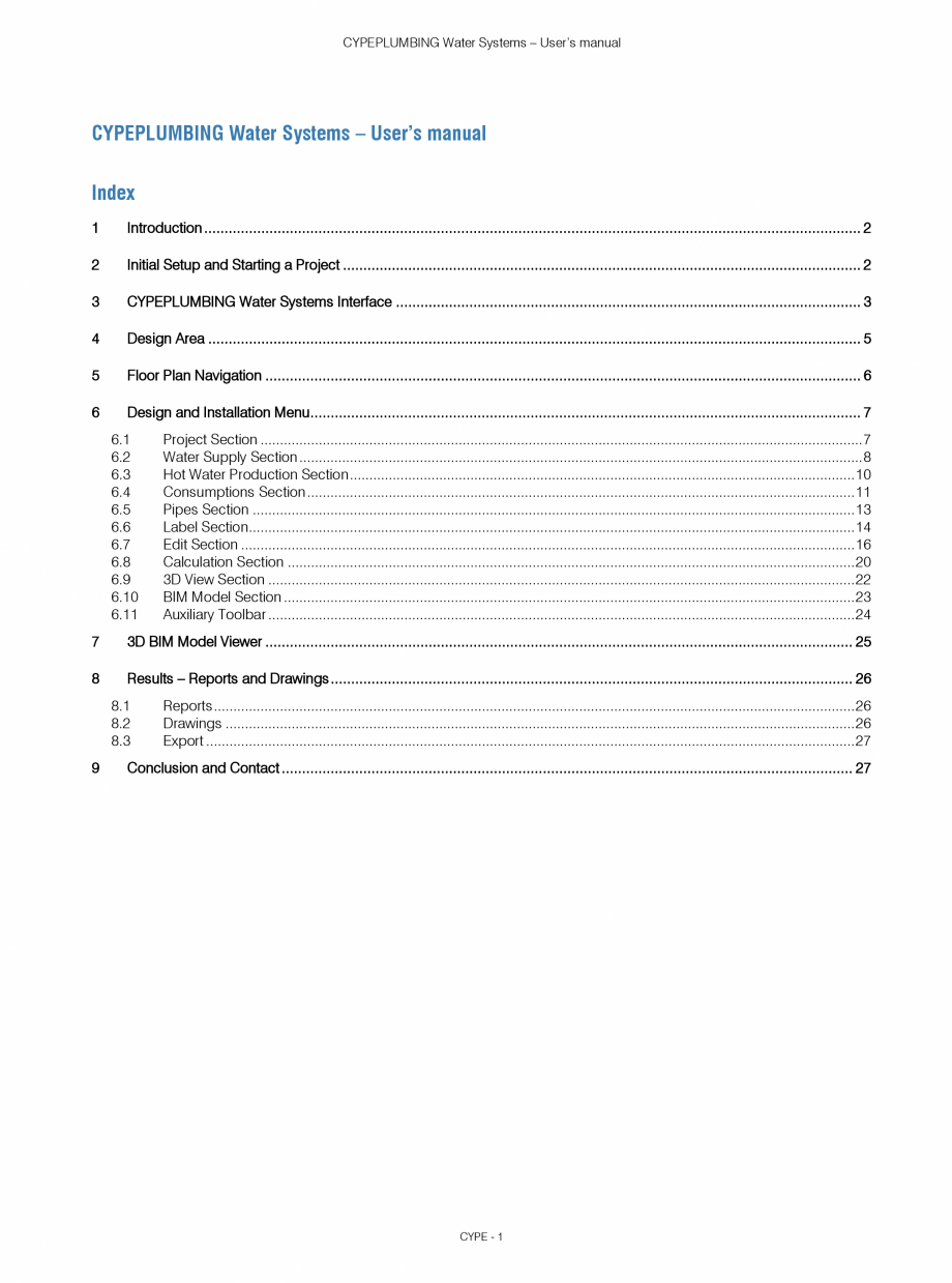
Index
1
Introduction ................................................................................................................................................................. 2
2
Initial Setup and Starting a Project ............................................................................................................................... 2
3
CYPEPLUMBING Water Systems Interface .................................................................................................................. 3
4
Design Area ................................................................................................................................................................ 5
5
Floor Plan Navigation .................................................................................................................................................. 6
6
Design and Installation Menu ...
.................................................................................................................................... 7
6.1
6.2
6.3
6.4
6.5
6.6
6.7
6.8
6.9
6.10
6.11
Project Section ........................................................................................................................................................... 7
Water Supply Section ................................................................................................................................................. 8
Hot Water Production Section .................................................................................................................................. 10
Consumptions Section ............................................................................................................................................. 11
Pipes Section ....................................................................................................................................
....................... 13
Label Section............................................................................................................................................................ 14
Edit Section .............................................................................................................................................................. 16
Calculation Section .................................................................................................................................................. 20
3D View Section ....................................................................................................................................................... 22
BIM Model Section ................................................................................................................................................... 23
Auxiliary Toolbar .................................................................................................
...................................................... 24
7
3D BIM Model Viewer ................................................................................................................................................ 25
8
Results – Reports and Drawings ................................................................................................................................ 26
8.1
8.2
8.3
9
Reports ..................................................................................................................................................................... 26
Drawings .................................................................................................................................................................. 26
Export ....................................................................................................................................................................... 27
Conclusion and Contact ...............................
............................................................................................................. 27
CYPE - 1
CYPEPLUMBING Water Systems – User’s manual
1
Introduction
Thank you for choosing CYPE and CYPEPLUMBING Water Systems. CYPEPLUMBING Water Systems is a program created
for the design and analysis of potable water supply installations. This system is integrated in the Open BIM workflow via the
BIMserver.center using the IFC standard. CYPEPLUMBING Water Systems can perform a partial or complete design
installation of any building type. In this program, there are predefined equipment configurations as well as the option for
users to create their own custom equipment configurations. Users can design a water system installation in a 2D workspace
with 3D viewing; conduct automated calculations and checks based off predefined or custom installation configurations;
graphically analyze the results; and obtain various drawings, diagrams, and result reports.
Throughout
the remainder of the manual, more in-depth tutorial videos and descriptions of navigating the CYPEPLUMBING
Water Systems can be found.
2
Initial Setup and Starting a Project
This section of the manual is to show how to initially start a project and begin using CYPEPLUMBING Water Systems. Begin
by having CYPEPLUMBING Water Systems downloaded, a BIMserver.center account, and an accessible IFC file model.
The first step is to open CYPEPLUMBING Water Systems. Next, connect to BIMserver.center on the far right side and sign in
if needed by following the prompted steps. Once signed in, a new project can be created and an IFC file can be imported.
To continue working on a file, select “File Manager” under File. Otherwise, to start a new project, select “New…” under File,
choose where the file will be saved under Browse, and give the file a name and description if desired. After continuing, a
screen will appear regarding BIMserver.center. Here is where a new project within BIMser
ver.center can be created by
selecting “Create new project” or a project can be continued by clicking on “Select project”. After the desired project is
selected or created, the next screens that appear are import settings and installation code parameters by country that can
be adjusted as needed. Following the completion of these screens, the IFC file should appear in CYPEPLUMBING Water
Systems and editing can begin.
It is encouraged to view this tutorial video on initial setup and starting a project if there are still any questions or a visual
guide is needed.
INITIAL SETUP AND STARTING A PROJECT (2 MINUTES AND 9 S ECONDS)
CYPE - 2
CYPEPLUMBING Water Systems – User’s manual
3
CYPEPLUMBING Water Systems Interface
The CYPEPLUMBING Water Systems interface comprises of four main areas: The Design Area, Floor Plan Navigation,
Design and Installation Menu, and 3D BIM Model Viewer. Pictures of each of the main areas, outlined in red, are below. All
four sections are explai
ned in greater detail throughout the remainder of this manual.
Figure 1 – Design Area
Figure 2 – Floor Plan Navigation
CYPE - 3
CYPEPLUMBING Water Systems – User’s manual
Figure 3 – Design and Installation Menu
Figure 4 – 3D BIM Model Viewer
CYPE - 4
CYPEPLUMBING Water Systems – User’s manual
4
Design Area
Figure 5 – Design Area
The Design Area of the interface is the central area (outlined in red above) in the CYPEPLUMBING Water Systems. This
section is the location for the design and editing of the model. The design of the water system installation is done in 2D
through this area of the interface. The other three interfaces of the Water Systems software are used to adjust and view
aspects of this area. The Design and Installation Menu is to make design changes and edits, the Floor Plan Navigation is to
adjust floor plans for the Design Area, and the 3D BIM Model Viewer is to view a mockup of the design.
When working in the Design Area, there are severa
l general navigation techniques. To select icons and other buttons within
this software, a left click is used. A left click is also used to select any items within the Design Area. A right click, however, is
used to exit a current task or to access the popup window if there are settings available for the icon in use. The scroll wheel
of the mouse moves the view in or out. Lastly, the center scroll wheel pans the Design Area´s window when pressed and the
mouse is moved simultaneously.
A brief tutorial video on basic navigation techniques within the Design Area can be viewed in the link below.
D ESIGN AREA (55 S ECONDS)
CYPE - 5
CYPEPLUMBING Water Systems – User’s manual
5
Floor Plan Navigation
Figure 6 – Floor Plan Navigation
The Floor Plan Navigation area of the interface is the middle left toolbar (outlined in red above) in the CYPEPLUMBING
Water Systems. This section serves as the location for information and navigation through floor plans, individual floor levels,
and
the related settings. In this area of the interface, it is possible to move between floors, rearrange the order of floor plans,
add or delete floor plans, duplicate floor plans, and lastly edit the floor plans such as the elevation and the height of
installation. The video link below provides a brief walkthrough on this section and how it pertains to the interface and the
model.
F LOOR PLAN NAVIGATION (40 S ECONDS)
CYPE - 6
CYPEPLUMBING Water Systems – User’s manual
6
Design and Installation Menu
Figure 7 – Design and Installation Menu
The Design and Installation Menu is the top toolbar (outlined in red above) in the CYPEPLUMBING Water Systems. This
toolbar serves as the location for most of the necessary design tools, settings, and calculations. This menu is utilized in most
actions when designing and analyzing a water system installation.
The Design and Installation Menu is divided into multiple sections. These sections are: Project, Water Supply, Hot Water
Production,
Consumptions, Pipes, Label, Edit, Calculation, 3D View, BIM Model, and lastly there is an Auxiliary Toolbar.
Detailed descriptions and tutorial videos on each of these sections can be viewed below.
6.1
Project Section
The Project Section of the Design and Installation Menu is the location where most initial installation design options can be
configured. In the “General Settings” tab, a popup appears on screen that adjusts analysis and drawing options, material
and equipment selection, design and checks to be carried out, and installation codes by country. It is recommended to go
into the “General Settings” and go through each settings box to confirm the defined options are the desired options before
beginning the project. A tutorial video has been provided below which provides a more in-depth explanation of the Project
Section and the “General Settings” tab.
Figure 8 – Project Section
CYPE - 7
CYPEPLUMBING Water Systems – User’s manual
Figure 9 – Project Se
ttings General Settings
PROJECT S ECTION (3 MINUTES AND 43 SECONDS)
6.2
Water Supply Section
The Water Supply Section is the location within the toolbar to access all water supply equipment and to install, design, and
adjust its settings. In this section, design additions and setting adjustments for supply connection points, meters,
accessories, tanks, and pump systems are made. A tutorial video explaining the features and icons of this section can be
viewed by following the link below.
Figure 10 – Water Supply Section
W ATER S UPPLY S ECTION (5 MINUTES AND 40 SECONDS)
CYPE - 8
CYPEPLUMBING Water Systems – User’s manual
Supply Connection Point
A supply connection point can be added to the design by clicking on the icon, verifying the supply information, and left
clicking in the design to place the equipment. The information that is able to be viewed when selecting the icon is the
general data of the equipment, any checks to be verified, the 3D installation arrangement,
and the label. When placing the
equipment in the design, a toolbar will appear on screen with various arrows. Select the appropriate arrow to rotate the
equipment to the proper orientation to be placed in the installation.
Figure 11 – Supply Connection Point Icon
Meter
A meter can be added to the design by clicking on the icon, verifying the meter information, and left clicking in the design to
place the equipment. The information that is able to be viewed when selecting the icon is the general data of the equipment,
the meter information, and the label. When placing the equipment in the design, a toolbar will appear on screen with various
arrows. Select the appropriate arrow to rotate the equipment to the proper orientation to be placed in the installation.
Figure 12 – Meter Icon
Accessory
An accessory, such as a valve, can be added to the design by clicking on the icon, verifying the accessory information, and
left clicking in the design to place the equipment. The informatio
n that is able to be viewed when selecting the icon is the
type of accessory, the general data of the equipment, the 3D installation arrangement, and the label. When placing the
equipment in the design, a toolbar will appear on screen with various arrows. Select the appropriate arrow to rotate the
equipment to the proper orientation to be placed in the installation.
Figure 13 – Accessory Icon
Tank
A tank can be added to the design by clicking on the icon, verifying the tank information, and left clicking in the design to
place the equipment. The information that is able to be viewed when selecting the icon is the general data of the equipment,
any checks to be verified, the 3D installation arrangement, and the label. When placing the equipment in the design, a
toolbar will appear on screen with various arrows. Select the appropriate arrow to rotate the equipment to the proper
orientation to be placed in the installation.
Figure 14 – Tank Icon
CYPE - 9
CYPEPLUMBING Water Syste
ms – User’s manual
Pump System
A pump system can be added to the design by clicking on the icon, verifying the system information, and left clicking in the
design to place the equipment. The information that is able to be viewed when selecting the icon is the type of pump
system, the general data of the equipment, the 3D installation arrangement, any checks to be verified, and the label. When
placing the equipment in the design, a toolbar will appear on screen with various arrows. Select the appropriate arrow to
rotate the equipment to the proper orientation to be placed in the installation.
Figure 15 – Pump System Icon
Drop Down Tab
In the Water Supply Section, there is a drop down tab in the bottom right corner of the section. When selecting the tab, a
window appears allowing adjustments to any water supply equipment settings as well as additions to any custom water
supply equipment that is not currently preloaded into CYPEPLUMBING Water Systems. It is recommended to view th
e
tutorial for this section for a more detailed, visual explanation.
Figure 16 – Drop Down Tab
6.3
Hot Water Production Section
In the Hot Water Production Section, the installation, design, and setting adjustment for the hot water production equipment
can be completed. Hot water production units and setting adjustments of those units are done from this section. A video
explaining the features and icons of this section can be viewed from the link below.
Figure 17 – Hot Water Production Section
H OT WATER PRODUCTION S ECTION (2 MINUTES AND 27 S ECONDS)
Hot Water Production
This icon allows for the addition of a hot water production unit to the design. The type of water heater, the specifications and
general settings, and viewing of any checks that will be performed are chosen from this icon. To add a unit, select the icon,
verify the type of unit and settings, and left click in the design the desired location to place the equipment. When placing the
equipment in the design, a
toolbar will appear on screen with various arrows. Select the appropriate arrow to rotate the
equipment to the proper orientation to be placed in the installation.
CYPE - 10
CYPEPLUMBING Water Systems – User’s manual
Figure 18 – Hot Water Production Icon
Water Heater and Instant Water Heater Shortcut
These next two icons act as shortcuts for adding hot water production units to the design. Place the cursor over the icon to
view which shortcut is available. Simply click on the icon to add the selected unit to the design. These two icons do not
display any checks to be consulted or any 3D installation arrangement options. To verify or change those, the installation of
these units must be done through the main “Hot Water Production” icon.
Figure 19 – Hot Water Production Shortcut Icons
Drop Down Tab
By selecting the drop down tab from the bottom right corner of the section, a window appears allowing for the adjustment to
any hot water production equipment as well as the
addition of any custom hot water production equipment that is not
currently preloaded into CYPEPLUMBING Water Systems. It is recommended to view the tutorial for this section for a more
detailed, visual explanation.
Figure 20 – Drop Down Tab
6.4
Consumptions Section
The Consumptions Section is the location of the installation, design, and configuration for all water consumption equipment.
There is a main consumption icon to access all consumption units as well as many shortcut icons to specific units. A video
explaining the features and icons of this section can be viewed from the link below.
Figure 21 – Consumptions Section
C ONSUMPTIONS S ECTION (2 MINUTES AND 4 S ECONDS)
CYPE - 11
CYPEPLUMBING Water Systems – User’s manual
Consumption
The main consumption icon is selected to choose the type of consumption, adjust any general data, and verify any checks
that will be performed. To add a unit, select the icon, verify the type of unit and settings, and left click in t
he design the
desired location to place the equipment. When placing the equipment in the design, a toolbar will appear on screen with
various arrows. Select the appropriate arrow to rotate the equipment to the proper orientation to be placed in the installation.
Figure 22 – Consumption Icon
Consumption Equipment Shortcut
The smaller icons to the right in this section correspond to shortcuts for select consumption equipment. These icons bypass
any popup windows and do not display any general data or checks. Rather, after selecting the icon, the equipment is placed
right into the design. If any changes or information about the consumption unit needs to be viewed, click on the large
“Consumption” icon instead.
Figure 23 – Consumption Equipment Shortcut Icons
Drop Down Tab
By selecting the drop down tab from the bottom right corner of the section, a window appears allowing for the adjustment to
any consumption equipment as well as the addition of any custom consumption equipmen
t that is not currently preloaded
into CYPEPLUMBING Water Systems. It is recommended to view the tutorial for this section for a more detailed, visual
explanation.
Figure 24 – Drop Down Tab
CYPE - 12
CYPEPLUMBING Water Systems – User’s manual
6.5
Pipes Section
To the right of the Consumptions is the Pipes Section of the Design and Installation Menu. The Pipes Section is where
horizontal and vertical pipes can be installed and their settings altered if needed. Also in this section is where an insertion
point can be added or pipes can be joined. A video explaining the features and icons of this section can be viewed from the
link below.
Figure 25 – Pipes Section
PIPES SECTION (4 MINUTES AND 9 S ECONDS)
Horizontal Pipe
Select this icon to add a horizontal pipe to the design. A popup window will appear where the type of pipe can be
configured. This configuration allows for the selection of whether the pipe carries hot or cold water, viewing of the general
data of the pipe
, establishing the 3D configuration, and viewing any checks that will be made by the software. After
accepting the conditions in this window, the pipe can be added to the installation by left clicking.
Figure 26 – Horizontal Pipe Icon
Vertical Pipe
Select this icon to add a vertical pipe to the design. A popup window will appear where the type of pipe can be configured.
This configuration allows for the selection of whether the pipe carries hot or cold water, viewing of the general data of the
pipe, establishing the 3D configuration, and viewing any checks that will be made by the software. After accepting the
conditions in this window, the pipe can be added to the installation by left clicking.
Figure 27 – Vertical Pipe Icon
Insert Point
The “Insert Point” icon, located in the top right corner of this section, is selected when an existing pipe wants to be split into
sections. New pipes can also be branched from this new insertion point. To insert a point, select the icon,
click on the exact
location to place the point within the desired pipe, move the cursor outside of the pipe to confirm the location, and click a
second time on the desired location to place the insertion point.
CYPE - 13
CYPEPLUMBING Water Systems – User’s manual
Figure 28 – Insert Point Icon
Join Elements
The “Join Elements” icon, located in the lower right corner of this section, is selected when two separate, yet touching, pipes
are to be joined into a single pipe. Simply select the icon and click on the two pipes to be joined.
Figure 29 – Join Elements Icon
Drop Down Tab
By selecting the drop down tab from the bottom right corner of the section, a window appears to adjust any piping
equipment as well as add any custom piping equipment that is not currently preloaded into CYPEPLUMBING Water
Systems. It is recommended to view the tutorial for this section for a more detailed, visual explanation.
Figure 30 – Drop Down Tab
6.6
Label Section
Changes and modificat
ions to labels within the installation can be done by utilizing the tools in the Label Section of the
Design and Installation Menu. A video explaining the features and icons of this section can be viewed from the link below.
Figure 31 – Label Section
LABEL SECTION (1 MINUTE AND 46 S ECONDS)
CYPE - 14
CYPEPLUMBING Water Systems – User’s manual
Move Tag
In the top left of the Label Section is the “Move Tag” icon. This icon moves the current installation labels to a desired location
when selected. When selecting this icon, all available labels appear with a box in them. Left clicking on the available boxes
moves the label to the desired location.
Figure 32 – Move Tag Icon
Show/Hide Tag
In the bottom left of the Label Section is the “Show/Hide Tag” icon. This icon, as the name suggests, hides or shows
selected labels in the model. After pressing this icon to hide or show labels, labels can be selected individually by left
clicking on the labels or multiple can be se
lected at once by holding a left click to drag a box around multiple labels.
Figure 33 – Show/Hide Tag Icon
Place or Remove the Reference Line of the Tag
In the top right is the “Place or Remove the Reference Line of the Tag” icon. When selected, this icon adds or removes a
reference line to a label. If a reference line is added and the label is to be moved as well, the reference line will automatically
adjust to any label movement. To add a reference line, select the icon, and left click on any present label. Sometimes the
“Move Tag” icon needs to be utilized after adding a reference line to better view the line.
Figure 34 – Place or Remove the Reference Line of the Tag Icon
Rotate Tag
In the bottom right is the “Rotate Tag” icon. This tool rotates a desired label a specified amount in the model when selected.
To use this tool, select the icon, left click on an available label, and lastly rotate the label to the specified position.
Figure 35 – Rotate Tag Icon
D
rop Down Tab
By selecting the drop down tab from the bottom right corner of the section, a window appears to adjust labeling settings
such as what appears on the screen and how installation equipment is labeled. It is recommended to view the tutorial for
this section for a more detailed, visual explanation.
Figure 36 – Drop Down Tab
CYPE - 15
CYPEPLUMBING Water Systems – User’s manual
6.7
Edit Section
The Edit Section of the Design and Installation Menu is where to adjust existing components of the water system installation.
A brief explanation of each icon is explained, but it is recommended to view the tutorial video below for a more in-depth
explanation and a visual example of each.
Figure 37 – Edit Section
E DIT SECTION (7 MINUTES AND 26 S ECONDS)
Edit
The first icon is the “Edit” icon in the top left. This icon, when selected, allows for the viewing and editing of the properties of
any selected element within the work area. After selecting the icon, left click
on any element to view and edit its properties.
Figure 38 – Edit Icon
Delete
Below that icon in the toolbar is the “Delete” icon. When selected, this tool deletes any selected element within the work
area, with the exception of labels. To delete elements from the design, select the icon, left click on the elements to be
deleted, and right click once all desired elements have been selected and highlighted.
Figure 39 – Delete Icon
Move
To the right of the “Edit” icon is the “Move” icon. This tool moves any individual selected item in the work area with the
exception of labels. To move an item, select the icon and move any element by left clicking on it. You can move elements at
their connection points or at a place within the element.
Figure 40 – Move Icon
CYPE - 16
CYPEPLUMBING Water Systems – User’s manual
Rotate
Below the “Move” icon is the “Rotate” icon. This icon rotates any selected element a specified amount, with the exception of
pipes and
labels. To rotate an element, select the icon, left click on the element to rotate, move the cursor to the desired
rotation, and left click to complete the rotation.
Figure 41 – Rotate Icon
Illuminate 3D
The “Illuminate 3D” icon is a tool that can be used to highlight one or more water system installation elements in the 3D
viewer on the bottom left side of the software interface. To highlight the elements in orange in the 3D viewer, select the icon,
then left click on any element or drag the left click to make a box around multiple elements. Once selected, the elements will
automatically be highlighted in the 3D viewer.
Figure 42 – Illuminate 3D Icon
Measure Lengths on Plan
To measure lengths and areas within the design area of the software interface, the “Measure Lengths on Plan” icon is used.
This icon measures any length by left clicking on a desired spot in the design area to begin an on-screen measurement. Left
click each time a new point is to be made.
Figure 43
... ascunde
Alte documentatii ale aceleasi game Vezi toate
Fisa tehnica
48 p | EN
CYPE 3D
Fisa tehnica
44 p | EN
CYPE 3D