Perdea de aer arhitecturala pentru usi rotative TEDDINGTON RONDO
DESIGN
T E C H N I C A L D ATA
AIR
f o r
C U R T A IN
E X L U S I V E
U NI T S
R E Q U I R E M EN T S
Teddington
TEDDINGTON
Overview of Designer Air Curtain Systems
It depends on the situation.
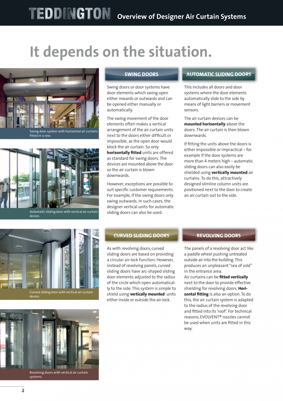
SWING DOORS
AutomatiC SLIDING DOORS
Swing doors or door systems have
door elements which swing open
either inwards or outwards and can
be opened either manually or
automatically.
S
wing door system with horizontal air curtains
fitted in a row.
Automatic sliding door with vertical air curtain
device.
This includes all doors and door
systems where the door elements
automatically slide to the side by
means of light barriers or movement
sensors.
The swing movement of the door
elements often makes a vertical
arrangement of the air curtain units
next to the doors either difficult or
impossible, as the open door would
block the air curtain. So only
horizontally fitted units are offered
as standard for swing doors. The
devices are mounted above the door
so the air curtain is blown
down
wards.
The air curtain devices can be
mounted horizontally above the
doors. The air curtain is then blown
downwards.
However, exceptions are possible to
suit specific customer requirements.
For example, if the swing doors only
swing outwards. In such cases, the
designer vertical units for automatic
sliding doors can also be used.
If fitting the units above the doors is
either impossible or impractical – for
example if the door systems are
more than 4 meters high – automatic
sliding doors can also easily be
shielded using vertically mounted air
curtains. To do this, attractively
designed slimline column units are
positioned next to the door to create
an air curtain out to the side.
Curved sliding doors
C
urved sliding door with vertical air curtain
device.
Revolving doors with vertical air curtain
systems.
2
REVOLVING DOORS
As with revolving doors, curved
sliding doors are based on providing
a circular air-lock function. However,
instead of revolving panels, curved
slidin
g doors have arc-shaped sliding
door elements adjusted to the radius
of the circle which open automatically to the side. This system is simple to
shield using vertically mounted units
either inside or outside the air-lock.
The panels of a revolving door act like
a paddle wheel pushing untreated
outside air into the building. This
produces an unpleasant “sea of cold”
in the entrance area.
Air curtains can be fitted vertically
next to the door to provide effective
shielding for revolving doors. Horizontal fitting is also an option. To do
this, the air curtain system is adapted
to the radius of the revolving door
and fitted into its ‘roof’. For technical
reasons, EVOLVENT® nozzles cannot
be used when units are fitted in this
way.
Overview of units.
D o o r s i tuat i o n
Unit series
Page
DELTA
4-5
ELLIPSE
6-9
SILENT
10-13
DELTA
4-5
ELLIPSE
6-9
SILENT
10-13
CHARISMA
14-19
TOPAS
20-21
SINTRA
22-23
SINTRA
22-23
SAPHIR
24-25
Vertical
SAPHIR
24-25
Hor
izontal
SWING DOORS
A ss e m b l y
RONDO
26-29
Horizontal / Vertical
ALL
30-35
HORIZONTAL
Horizontal
Automatic sliding doors
VertiCal
Curved sliding doors
VertiCal
REVOLVING DOORS
ACCESSORIES / CONTROLLERS
3
RONDO
Designer Units for Horizontal Fitting
R E VO LV I N G
D O O R S
Technical data
Type
Rondo 1
Rondo 2
2.5
2.8
Rondo 3
Max. installation height
[m]
Width
[cm]
100
150
200
250
300
100
150
200
250
300
3.5
[m³/h]
1800
2700
4500
5400
6300
2700
3600
5400
6300
7200
[dB(A)]
54
55
56
57
58
55
56
57
58
60
100
150
200
250
300
Air volume
Nominal volume flow
3800 4900
7200
9500 11000
Noise level in a distance of 3m
56
58
59
60
61
Electrical data
Voltage
[V]
230
230
230
230
230
230
230
230
230
230
230
230
230
230
230
Power output
[kW]
0.39
0.59
0.99
1.18
1.38
0.59
0.79
1.18
1.38
1.58
0.81
1.30
1.96
2.61
3.26
Current
[A]
1.71
2.57
4.29
5.14
6.00
2.57
3.43
5.14
6.00
6.86
3.35
6.09
9.14
12.18
15.23
[kg]
40
50
75
95
110
42
65
80
100
120
100
135
170
200
230
Approximate weight
Heater battery technical data
PWW 70/50 air intake temperature of 20°C and air discharge temperature of 37°C
Heater power
[kW]
10.3
15.4
25.6
30.8
36.0
13.4
19.5
30.6
36.0
41.2
21.7
28.0
41.1
54.7
62.8
Through flow rate
[m³/h]
0.45
0.68
1.14
1.36
1.60
0.59
0.85
1.34
1.58
1.81
0.95
1.23
1.80
2.40
2.76
Water resistance
[kPa]
2.08
1.96
3.10
2.93
2.78
3.33
2.94
4.23
3.84
3.50
3.40
2.80
3.13
3.23
3.25
82.7
PWW 70/50 air intake temperature of 15°C and maximum air discharge temperature
Heater power
[kW]
12.3
19.1
31.7
39.4
47.1
15.6
22.6
35.3
43.3
51.1
28.6
36.9
54.2
71.5
Air discharge temperature
[°C]
35.0
35.6
35.6
36.4
36.9
31.9
33.4
34.1
35.1
35.8
37.0
37.0
37.0
37.0
37.0
Through flow rate
[m³/h]
0.54
0.84
1.39
1.73
2.07
0.68
0.99
1.55
1.90
2.24
1.25
1.62
2.38
3
.13
3.63
Water resistance
[kPa]
2.87
2.83
4.51
4.48
4.45
4.33
3.82
5.46
5.28
5.14
5.51
4.55
5.05
5.18
5.30
65.2
PWW 60/40 air intake temperature of 20°C and maximum air discharge temperature
Heater power
[kW]
7.0
10.9
18.6
23.3
27.9
8.8
12.9
20.7
25.5
30.2
19.3
27.3
41.7
54.7
Air discharge temperature
[°C]
31.6
32.0
32.3
32.8
33.2
29.7
30.7
31.4
32.0
32.5
35.1
36.6
37.2
37.1
37.6
Through flow rate
[m³/h]
0.31
0.48
0.81
1.02
1.22
0.39
0.56
0.90
1.11
1.32
0.84
1.19
1.82
2.39
2.85
Water resistance
[kPa]
1.10
1.10
1.83
1.84
1.83
1.65
1.48
2.20
2.15
2.11
2.86
2.77
3.31
3.34
3.58
Upstream
[inch]
3/4
3/4
3/4
3/4
3/4
3/4
3/4
3/4
3/4
3/4
3/4
3/4
3/4
3/4
3/4
Downstream
[inch]
3/4
3/4
3/4
3/4
3/4
3/4
3/4
3/4
3/4
3/4
3/4
3/4
3/4
3/4
3/4
Pipe connections
Electrical heater (three-step, 400 V, 3 Ph, 50 Hz)
Step 1
[kW]
4.5
6.0
12.0
12.0
12.0
6.0
9.0
12.0
12.0
12.0
9.0
12.0
12.0
12.0
12.0
Step 2
[kW]
7.5
12.0
15.0
24.0
24.0
12.0
15.0
24.0
24.0
24.0
15.0
18.0
24.0
24.0
24.0
Step 3
[kW]
12.0
18.0
27.0
36.0
36.0
18.0
24.0
36.0
36.0
36.0
24.0
30.0
36.0
36.0
36.0
∆t max.
[K]
18.6
18.6
16.7
18.6
15.9
18.6
18.6
18.6
15.9
14.0
17.6
17.1
14.0
10.6
9.1
Width BL
[mm]
1000
1500
2000
2500
3000
1000
1500
2000
2500
3000
1000
1500
2000
2500
3000
Height H
[mm]
240
240
240
240
240
240
240
240
240
240
410
410
410
410
410
Depth T
[mm]
400
400
400
400
400
400
400
400
400
400
580
580
580
580
580
Dimensions
Selection table
Door diameter
1.8
2.0
2.2
2.3
2.4
2.9
Rondo 1-100
Installation height up to 2,5
Opening
Installation height up to 2,8
angle 60°
3.0
3.1
3.2
Rondo 2-100
Rondo 2-100
Rondo 2-100
Installation height up to 3,5
Installation height up to 2,5
2.8
Rondo
1-100
Rondo 2-100
Rondo
2-150
3.7
4.1
4.2
4.4
4.5
Rondo 1-150
Rondo 3-15
0
4.6
5.1
5.2
5.3
Rondo 2-200
Rondo 2-250
Rondo 3-200
Rondo 2-150
Rondo 2-200
Installation height up to 3,5
Rondo 3-100
Rondo 3-150
Rondo 3-200
Rondo 3-250
5.8
6.0
6.1
Rondo 2-250
Rondo 2-250
Rondo 1-250
Rondo 2-100
5.6
6.2
6.4
6.5
Rondo 1-250
Rondo 2-200
Rondo 1-200
Opening
Installation height up to 2,8
angle 90°
5.4
Rondo 1-200
Rondo 2-150
Rondo 3-100
Rondo 1-150
3.6
Rondo 2-300
Rondo 3-250
Rondo 1-300
Rondo 2-300
Rondo 2-300
Rondo 3-300
Rondo 3-300
This table is intended to provide an approximate pre-selection of a Rondo air curtain device. It is not binding! Variances, depending on the door construction and/
or building situation, may occur. Starting with a door diameter of 5.00 m and an opening angle of 90°, the air discharge duct and the blind are each produced
from 2 parts.
26
Downstream
BL
Upstream
T
Suction
grid
Filter
T
Adjusting screw feet
Air discharge duct is adapted to dimensions
and round shape of the revolving door
H
Inspection door
Sectioned view
Air discharge
nozzle
Cover
Dimensions - Type SDA
27
28
Upstream
H
Adjusting screw feet
Air discharge duct is adapted to dimensions
and round shape of the revolving door
Suction
grid
T
Inspection door
Air discharge
nozzle
R E VO LV I N G
BL
Downstream
T
Filter
Sectioned view
RONDO
Designer Units for Horizontal Fitting
D O O R S
Dimensions - Type SDE
RL
Downstream
BL
T
VL
Upstream
Suction
grid
Filter
M10
T
M10
Air discharge duct is adapted to dimensions and round shape of the revolving door
H
Sectioned view
Air discharge
nozzle
Dimensions - Type ZDE
29
TEDDINGTON
Designer Units for Horizontal / Vertical Fitting
Acce sso r i e s
/
Co ntro lle r s
Thermostats
Frost protection thermostat FTE
For protection of the hot water heater system, with capillary pipe sensor,
capillary pipe length 3 m, self-protecting as single-pole, potential-free toggle
switch, protection grade IP 30, built into the unit.
Electronic fr
ost protection thermostat FTM
Only in conjunction with controller units TCU, TC5 and TC3.
With capillary pipe sensor, capillary pipe length 0.9 m, protection grade IP 30,
built into the unit, only suitable for low-voltage applications (open contacts).
Electro-mechanic room air thermostat ERT
5 - 30 °C with bimetal, pure white (similar to colour RAL 9010), switching
capacity 230 V AC, 50...60 HZ, 10 A (4 A inductive) switching difference 0.5 K,
protection grade IP 30. Humidity 0...95 %, non condensing, operating temperature 0...40 °C, thermal feedbacks. Dimensions: 75 x 75 x 25 mm.
Repair switches
Repair switch REP-S
For switching off the equipment by software. Only in combination with controller units TCU, TC5 and TC3. Switch located behind the revision flap.
Repair switch REP-L
3 pole repair switch in wall mounting version, delivered as loose part for
installation at site in the connection cable.
Door contacts
Door contact type TK
Protection grade IP 65, jumper switch with H swi
tches and full contact up to
time of switching, shock-proof terminals according to VDE 0106, part 100
(VGB 4), cable gland 2 x PG 13.5 on underside and at side, switching voltage
230 V AC, 24 V DC, switching current 6 A AC, 4 A DC.
Door contact type TKB
Contact-less door contact with protection grade IP 00, consisting of reed
contact and permanent magnet for open circuit (contact open at applied
magnet), switching voltage 100 V DC, switching current 250 mA DC.
30
Controller/shut-off and magnetic valves
Regulating valve Type MR 2-E DN 20, built into the unit
Regulating valve MR-2 with electrical adjustment motor for regulation a
constant discharge temperature, including air discharge sensor, completely
installed and connected inside the air curtain device. The regulation valves
type MR-2 are special valves for regulation especially high quantities of water
(kvs-value at minimum 7.5). Connection DN 20.
Thermostatic control valve type KR 2-E DN 20, built into the unit
Special valve f
or controlling especially large water quantities;
kvs value 7.5. Capillary pipe length sensor 2 m, connection DN 20.
Thermostatic control valve type KR 3-L DN 20/25/32
Thermostatic control valve (three way valve) KR 3-L with thermostat head for
controlling of constant blow-out temperature, delivered as a loose part.
Special valve for controlling especially large water quantities. Capillary pipe
length sensor 2 m, DN 20 kvs 4.5; DN 25 kvs 6.5; DN 32 kvs 9.5.
Thermo electric shut-off valve Type TAV
230 V, closed at no current, delivered as a loose part for water shut-off via
summer/winter switch or for controlling the water through flow quantities
with controlling at site. Special valve for controlling especially large water
quantities; kvs value 5.5. Connection DN 20.
Magnetic valve MV
230 V, closed at no current, immediately closing, for water shut-off purposes
via summer/winter switch, delivered as a loose part.
DN 20 kvs 11; DN 25 kvs 13; DN 32 kvs 30.
Installation brackets
Ceiling installation bracket DH
Suspension bracket, vibration damper, threaded rods 1 m, securing and counter nut, anchor bolt, minimum space required 0.1 m, suspension length
1 m (number of items dependent on device length and type).
Comfort ceiling installation bracket DHD
Suspension bracket, vibration damper 17 dB, turnbuckle, right-left threaded
bolt, threaded rods 1 m, securing and counter nut, drive in dowel, minimum
space required 0.2 m, suspension length 1.1 m (number of items dependent
on device length and type).
31
TEDDINGTON
Designer Units for Horizontal / Vertical Fitting
Acce sso r i e s
/
Co ntro lle r s
Teddington Control Unit TCU
The TCU Controller Unit (for hot water devices) is a 5-step
or stepless speed controller with additional functions, to
enable adjustments in the air volume depending on the
various climatic weather conditions.
Functions / Properties:
• Release from the DDC/BMS
(direct digital control/building
management system)
• On/Off switc
h
• Integrated clock with
programmed switching time
periods
• Integrated room thermostat
• Potential free change-over contacts,
operational- and collective
disfunction message (16A)
• Integrated filter monitoring via
operating time or an external
signal
•
Manual and automatic function;
automatic e.g. door contact,
room thermostat, infrared
sensor, exterior thermostat
• Full motor protection; electronic
processing and signalling in cases
of motor failure
• Option: speed regulation through
external signal e.g. infrared
sensor or exterior thermostat
• Summer/winter switch to control
a magnetic valve or pump (with or
without heating medium)
• After run control via door
contact with adjustable after
run time ( 0-600 sec)
• Dimensions: L103 x W103 x D29 mm
• Error memory for tele-diagnoses
• Option: repair-switch, safety
shut-down switch
• Option: electronic air discharge
temperature control with digital
... ascunde
Alte documentatii ale aceleasi game Vezi toate
Fisa tehnica
16 p | EN
CHARISMA
Fisa tehnica
12 p | EN
DELTA