Placi HPL compact fatade MEG_GEPLAST ABET LAMINATI
Tip documentatie: Specificații tehnice
Salvează pdf
Full screen
up-to-date list of
concerned MEG Standard decors.
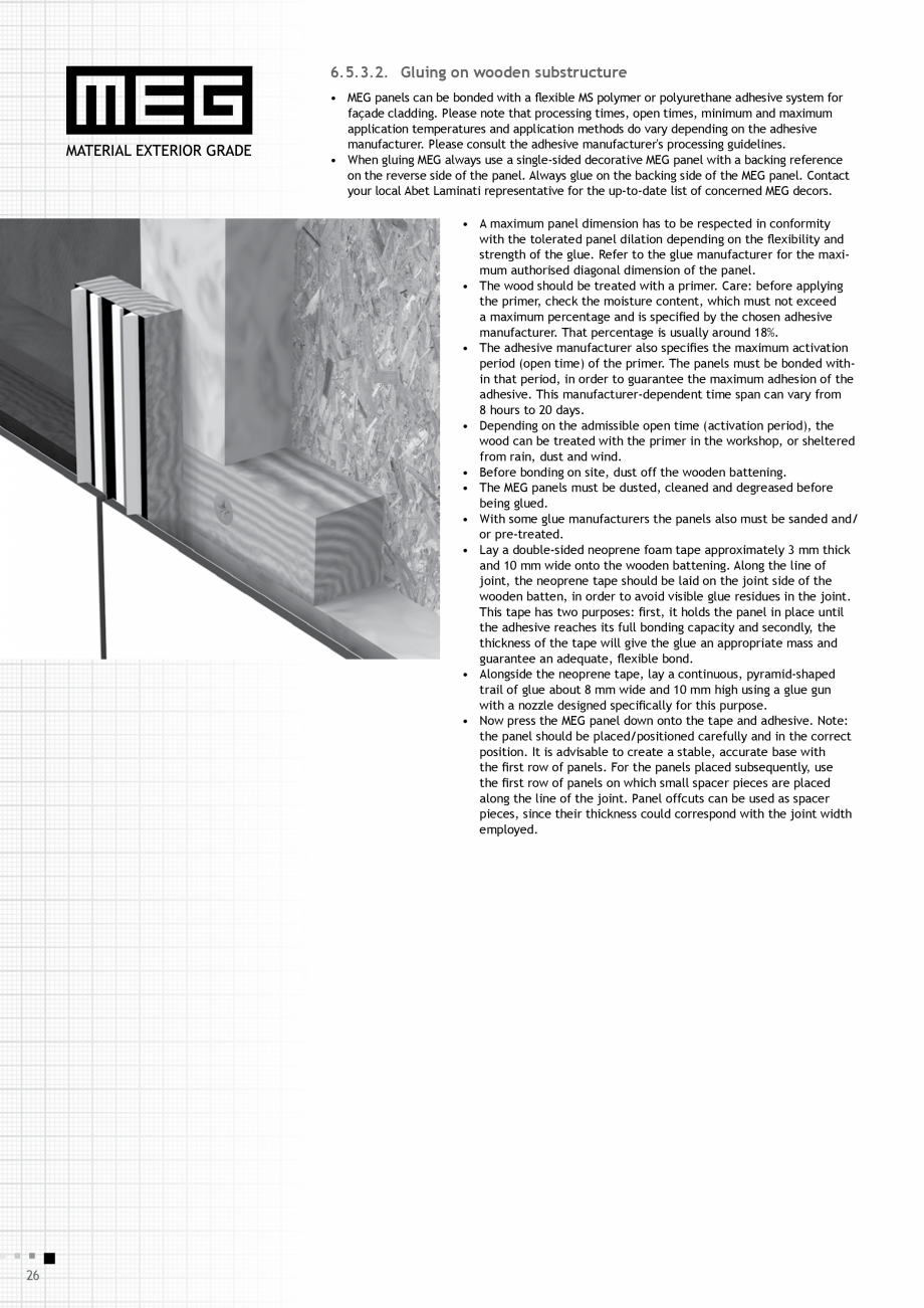
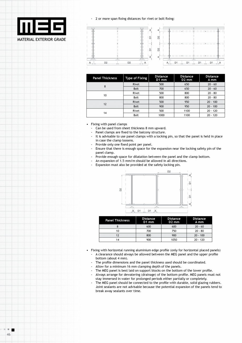
• A maximum panel dimension has to be respected in conformity
with the tolerated panel dilation depending on the flexibility
and strength of the glue. Refer to the glue manufacturer for the
maximum authorised diagonal dimension of the panel.
• Before bonding on site, dust, clean and degrease the aluminium
support structure.
• The MEG panels must be dusted, cleaned and degreased before
being glued.
• With some glue manufacturers the panels also must be sanded
and/or pre-treated.
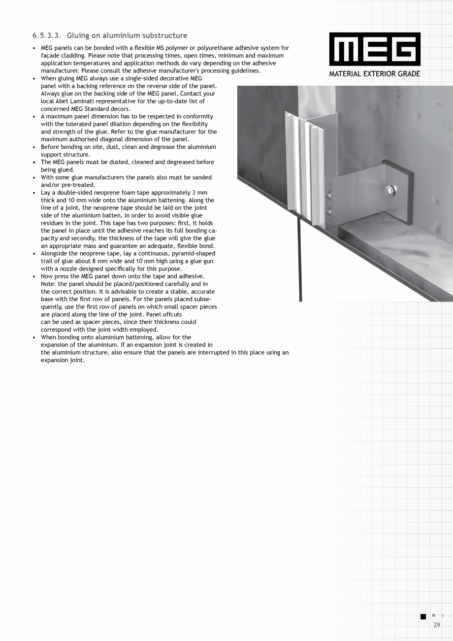
• Lay a double-sided neoprene foam tape approximately 3 mm
thick and 10 mm wide onto the aluminium battening. Along the
line of a joint, the neoprene tape should be laid on the joint
side of the aluminium batten, in order to avoid visible glue
residues in the joint. This tape has two purposes: first, it holds
the panel in place until the adhesive reaches its full bonding capacity and secondly, the thickness of the tape will give the glue
an appropriate
... ascunde
Alte documentatii ale aceleasi game
Catalog, brosura