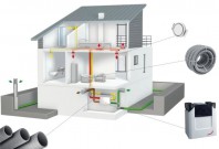
Unitati centrale de ventilatie cu schimbator de caldura rotativ Ensy Inovent AHU-200-700 ECOCALD Unitati centrale de ventilatie ECOCALD
Tip documentatie: Instructiuni montaj, utilizare
Salvează pdf
Full screen
User manual and
Installation Guide
InoVent AHU-200-700
393930-2 Rev 0: 01.04.2020
2|Page
393930-2 Rev 0: 01.04.2020
1
Read this first!
The contents of this manual are subject to change without notice.
ENSY® holds the copyright to this user’s manual. The user shall follow any instructions given in this user
manual entirely and not only partly. Any non-following of this user manual result in exclusion of all
warranties, guarantees, and liabilities.
Copyright© 2020 by ENSY® AS. All Rights Reserved.
Disposing of the parts of the controller:
INFORMATION FOR USERS ON THE CORRECT HANDLING OF WASTE ELECTRICAL AND ELECTRONIC
EQUIPMENT (WEEE)
Disposal must be in accordance with European Union directives and the related national legislation.
1.1
Reading instructions
The following symbols are used to draw the reader’s attention to different warning levels.
Important information
Danger!! General danger
Danger!! High voltage! Danger of electrical current or voltage
1.2
User
manual
Before installation the user should be thoroughly familiarized with this user manual, especially with
purposes, installation, settings and operation.
Special care should be taken when installing and connecting external equipment (sensor, high voltage
etc.) and handling the PCB’s correctly according to protection against ESD
Installation of the electronics/parts must be performed by authorized personnel only. All
warranties are excluded in case installation is performed by unauthorized personnel or in
case the spare parts have not been correctly installed.
3|Page
393930-2 Rev 0: 01.04.2020
2
Functions of the Air Handling Unit Controller
The Air Handling Unit controller is designed for domestic and smaller industrial ventilation systems. Heat
recovery can be either passive or active using a heat pump. Air heater can be added to either pre-heat or
after-heating the inlet air.
The air handling unit can also be extended with hot tap water production using a heat pump taking
energy
from the exhaust air.
Depending on the complexity and size of the ventilation system the following functionality is available:
• Ventilation control
• Temperature control
• Heat recovery – via rotor heat exchanger
• Air heater – after-heater
• Defrosting
• User functions
• Week program
• External heat source control
• Filter monitoring via pressure-drop measurement (optional)
2.1
Ventilation control
2.1.1 Start-up
Unit with outputs for air dampers can be configured for a delayed start of the ventilation fans. This gives the air
dampers time to be fully opened before pressure builds up. Via a menu the ventilation start delay can be
adjusted. Inlet starts another 1 minute after the exhaust fan has started.
If low winter ventilation is activated, the unit will always start up at the selected winter low step the first 2
minutes.
2.1.2 Ventilation based on humidity and CO2 level
A humidity sensor (included) and a CO2 level sensor (optional) can be connected
to the unit controller. The
controller will adjust ventilation based on the desired settings in the Air quality menu.
The installer configures the humidity levels where ventilation should change speed either up or down.
NOTE! REMOVE THE DUST CAP FROM THE SENSOR AFTER THE UNIT WAS INSTALLED!!!
In the same menu the settings for ensuring a comfortable CO2 level can be configured. There are two CO2 levels,
a normal level and a high level where the ventilation speed will be increased.
Both sensors have 3 minutes settling time after start from ventilation step Off. Average = 24 hours average. RH
(high) = Average + 10%; RH (low) = average + 3%
2.2
Temperature control
2.2.1 Low room temperature alarm
This function ensures the room temperature is not getting too cold. If the room temperature is getting below
the room low-temperature limit, the inlet speed is reduced 1 step. After 5 minutes the speed is reduced
again until temperature can be maintained.
If the room temperature cannot be main
tained, the fans are stopped, and a Low Room Temp warning is set.
An external room temperature sensor is mounted.
The function can be disabled by setting the Room low limit to off in the Room control menu.
2.2.2 Summer/Winter operation
The controller can automatically switch between summer and winter operation based on the outdoor
temperature. After each shift, the unit stays here for 15 min before another shift is allowed.
The difference between summer/winter operations is the minimum temperature of the inlet air and that the
bypass damper is normally not opened in wintertime.
2.2.3 Control sensor
The controller can use different controlling sensors. Supply: The inlet temperature sensor is used; there is no
room temperature control. Extract: The extract temperature sensor is used.
4|Page
393930-2 Rev 0: 01.04.2020
2.3
Air heater (after-heater)
The air heater (or after heater) heats up the air after the air has passed the heat exchanger. It must be enabled
and configured in th
e Air heater menu.
The heater can be None or Electrical.
The electrical heater has a 0 – 10V analogue output and the heater relay is turned on when the heater is
needed.
2.4
Defrosting
Defrosting is done for 6 minutes every hour. During defrost, the supply fan is stopped, the exhaust fan is
running at MIN speed, the air heater is off and rotor speed is normal.
• Mode 1 is for low humidity and starts at -20⁰C
• Mode 2 is for normal humidity and starts at -15⁰C
• Mode 3 is for high humidity and starts at -10⁰C
After defrosting, the air heater is first started when fans are up and running
2.5
User selection functions
Activating the User function digital input can trigger different functions.
The air handling unit will perform this operation during the selected period and overriding the other user
settings including week program settings.
Function
Duration
None
Fan boost
Supply air (increase
supply air)
Extract air (increase
extract air)
Extern alarm
No action
Input
active
15 min – 8h
2.6
15 min – 8h
15 min – 8h
Supply air
level
MAX
Off, MIN, NORM,
MAX
NORM
Exhaust fan
level
MAX
NORM
Off, MIN,
NORM, MAX
Off, MIN, NORM, MAX
Cooker hood function
There is a separate digital input for the operation together with a turned-on cooker hood extractor.
Function
Duration
Supply air
Exhaust fan level
level
None
No action
Cooker hood
Input active 0-100%
0-100%
2.7
Rotor control
The rotor heat exchanger is always started some minutes before the heater. This ensures the rotor is first
started when the rotor alone is insufficient.
2.8 Party mode
The user can activate a party mode. It is used for increased ventilation with many people in the ventilated
area. Fan speed is set to MAX, the user can set it to MIN or NORM afterwards.
The existing set point is used. The user can change the set point during active party mode.
Party mode is automatically stopped when the party timeout period is over. Default timeout is 4 hours, it can
be changed after th
e activation. Party timeout menu is hidden when party mode is off.
2.9 Away mode
The away mode is for periods with low ventilation needs like away on holiday etc.
At activation, fan speed is set to MIN and set point to 15°C. Both fan speed and set point can be changed
afterwards. The Away mode must be turned off manually.
Fan speed and set point returns to the settings when the away mode was started.
5|Page
393930-2 Rev 0: 01.04.2020
3.
Menu system
3.1 Overview of the menu system
Main menu
Unit on/off
Fan speed
User selection
User
Set Point
10⁰C...26⁰
Alarm
Alar
Unit
Unit Information
Settings
Air
Week
Week program
Main screen
Normal /
Password
Readings
Reading
Servic
Service settings
Password
Date/time
Date/tim
Screen set.
Screen
Language
English / German /
Factor
Factory settings
French / Danish /
Norwegian / Polish
/
l
/
h/
Pressing the menu button will open several screens and menus. Press
go back to previous menu.
Press
and
buttons to scroll
up and down in the menus
If the alarm icon, is visible, pressing it will open the alarm menu
to
6|Page
393930-2 Rev 0: 01.04.2020
3.2 Main menu
The main screen is the default menu. The display returns to this
screen after some minutes without user interaction.
It shows the actual temperature, measured relative humidity and
actual fan speed.
A week program and an alarm are active on this example pressing
the button or the temperature will open the temperature set
point menu
Show the measured humidity
The fan speed can be adjusted by pressing the
speed
button or the
The user can select if the main menu should show a house
Touch the inlet arrow to set the desired temperature
3.3 Possible icons in the menu headline
Press the menu button to access the sub-menus
A week-program is active
One or more alarms are active
The air handling unit is turned off
Wi-Fi connection is not connected
7|Page
393930-2 Rev 0: 01.04.2020
4. User settings menu
This is the user level of the menu syst
em
Show run-mode
Touch to start and stop of the unit, On / Off
Show fan speed.
Touch to adjust fan speed; Off, MIN, NORM, MAX
Sub-menu with setup for different user configurable inputs
Turn Party mode on/off.
Increased fan speed for many people
Range: Off, On; default Off
Time out of Party mode. Only visible if Party mode is On.
Range 1 – 24 hours; default 4 hours
Turn Away mode on/off.
Reduced fan speed, MIN and lower set point 15°C
Range On, Off; default off
Show actual set point
Touch to adjust set point; range 10⁰C – 26⁰C
List, number of active alarms.
Open the alarm sub menu if there is an active alarm Submenu with software versions for the unit
8|Page
393930-2 Rev 0: 01.04.2020
Sub-menu with more user-settings
Sub-menu with temperatures and other operation data
Show and adjust date and time in a sub-menu
Adjust backlight levels in active and idle mode
Adjust display language.
Select between English, German, French, Danish, Norwegian, Polish, Italian,
Dutch and
Lithuanian
Week program sub-menu. Lists if a program is active
Switch between normal main menu and house main menu
Sub-menu with service settings. Password protected. Password is 5
Sub-menu with service settings. Password protected. Password is 50
9|Page
393930-2 Rev 0: 01.04.2020
4.1 User selection sub-menu
The unit has a digital input which can trigger a user- configurable function, i.
e. an increased fan speed when guests are coming. The input overrides the
normal operation
Select program: None, Fan boost, Supply air, Extract air, Extern alarm. Default
None
Menu only visible if a duration after activation can be set. Else function is
active when digital input is active.
Range Off: Until input is released; 15 min to 8 hours Menu visible for some
programs.
Set the fan speed to use when digital input is active
Range Off, MIN, NORM, MAX
4.2 Alarm handling menus
Sub-menu with warnings and critical alarms for the air handling unit.
Critical alarms will stop the unit. The unit may co
ntinue operation with a
warning.
it is a critical alarm and the air handling unit will
If the alarm icon is red ,
stop.
Touch to open a more detailed description
If the alarm icon is yellow , it is a warning and the air handling unit may
continue to operate
Touch to open a more detailed description
If the alarm icon is grey, , it is an inactive warning or critical alarm. The
alarm may have to be acknowledged to start the unit again.
Touch to open a more detailed description
Detailed description of a warning or critical alarm
Date/time the alarm came active
Touch Clear alarm to clear the alarm. If the alarm number starts with small
letters, c/w, the alarm can be cleared Alarm number, severity and description
Trouble shooting information for the alarm/warning
10 | P a g e
393930-2 Rev 0: 01.04.2020
List the software versions in the controller and display of the air handling
unit
Controller software version
Display software version
MAC address of the Wi-Fi radio
4.3 Settings for th
e air handling unit
Sub-menu for configuration of the cooker hood function. The air handling
unit will help push the steam towards the cooker hood
Set the temperature were the air handling unit switches to summer mode
Range 5⁰C.. 30⁰C; default 17⁰C
Set the minimum air inlet temperature in summer mode Range 5⁰C.. 50⁰C;
default 10⁰C
Set the minimum air inlet temperature in winter mode
Range 5⁰C .. 50⁰C; default 15⁰C
Set the maximum air inlet temperature in summer mode
Range 5⁰C .. 50⁰C; default 30⁰C
Set the maximum air inlet temperature in winter mode
Range 5⁰C .. 50⁰C; default 40⁰C
11 | P a g e
393930-2 Rev 0: 01.04.2020
Sub-menu for cooling recovery
Maximum rotor exchange speed Range 0% . 100%; default 100%
4.3.1
Cooker hood function
The air handling unit has a digital input for the cooker hood.
When the signal is active, the Supply and Extract fan speeds are
set to the specified speeds in 0-100%
Duration of the fan speeds after signal has disappe
ared. Range 00:00 (only
run when active signal);
1 min .. 1 hour 30 min; default 0 min
Supply fan speed during active cooker hood signal Range 0 – 100%; default
100%
Extract fan speed during active cooker hood signal Range 0 – 100%; default
100%
4.3.2
Cooling recovery function
Cooling recovery is used when the intake air temperature is
higher than the room temperature to keep the rooms cool.
Turn the cooling recovery mode On or Off Default
Off
Activate cooling recovery when the intake air temperature is
2⁰C or 3⁰C higher than the room temperature.
Range 2⁰C or 3⁰C
12 | P a g e
393930-2 Rev 0: 01.04.2020
4.4 Readings sub-menu
The menus contain readings for the sensors and outputs
Measured relative humidity
Supply air temperature
Extract air temperature
Air temperature at the air heater
Fresh air temperature
Exhaust air temperature (after the rotor heat exchanger)
Supply fan speed in percentage
Extract fan speed in percentage
Air heater percentage
13 | P a g e
3
93930-2 Rev 0: 01.04.2020
Speed of rotor heat exchanger
Pressure difference over the inlet air filter Used for filter clogging monitoring
(optional)
4.5 Date/time sub-menu
The controller has a built-in real time clock used for alarm
logging
Set the year
Set the month
Set the day of month
Set the hour (24h)
Set the minutes
14 | P a g e
393930-2 Rev 0: 01.04.2020
4.6 Screen settings
Set the backlight level when the display is active – being used
Set the backlight level in idle mode
Calibrate the touch panel only if the display responds unaligned
with finger touches!
Please note it must be done carefully as the display may else
become impossible to use!
4.7 Week program
The week program is used to program different fan speeds in up to 6 periods
per day and 3 different week programs, i. e. a normal week, holiday, a week
with shift-working hours
Select program 1, 2 or 3
Sub menu with program 1, 2 or 3 to edit
Reset selected program 1, 2, or 3 to default factory settings.
The
user will get a warning before applying the reset
Touch Program 1 to edit program 1 in sub-menus
Touch Program 2 to edit program 2 in sub-menus
Touch Program 3 to edit program 3 in sub-menus
15 | P a g e
393930-2 Rev 0: 01.04.2020
Every weekday can have its own 6 different profiles, typically
weekends are different
Touch to edit settings for Monday
Touch to edit settings for Tuesday
Touch to edit settings for Wednesday
Touch to edit settings for Thursday
Touch to edit settings for Friday
Touch to edit settings for Saturday
Touch to edit settings for Sunday
16 | P a g e
393930-2 Rev 0: 01.04.2020
Every function or profile has its own 3 settings: Start time, set point and fan
speed. When start time is reached, the set point is set to the entered value
and fan speed to the setting
Overview of function 1 on Monday
Touch to edit this function / profile
Overview of function 2 on Monday
Touch to edit this function / profile
Overview of function 3 on Monday
Touch to edit this functio
n / profile
Overview of function 4 on Monday
Touch to edit this function / profile
Overview of function 5 on Monday
Touch to edit this function / profile Off
means the function is not active
Overview of function 6 on Monday
Touch to edit this function / profile Off
means the function is not active
Touch to copy all 6 functions setting for the day, here Monday,
to the next day. Used if the next day should have the same
settings
17 | P a g e
393930-2 Rev 0: 01.04.2020
Every function / profile of the day has its own settings
Start time of the profile in 15 minutes interval
Range 00:15 to 23:45. 00:00 equals Off and means no function
Fan speed
Range Off, MIN, NORM, MAX
Level is hidden if Start time is Off
Desired temperature. Overwrites the main menu setting
Range 10°C to 26°C
Temperature is hidden if Start time is Off
Reset a program to default settings
Touch to reset program 1
Touch to reset program 2
Touch to reset program 3
Security question if you want to reset all settings
in the
program to default values
18 | P a g e
393930-2 Rev 0: 01.04.2020
Select if the main screen should be the house or the normal
view with lines
Accept or cancel
4.8 Service settings
Service settings are for the service technician and are password protected.
The default service password is 5
Accept change with
or decline with
Sub-menu with air handling settings
Sub-menu with calibration option of temperature sensors
Different counters for the air handling unit
19 | P a g e
393930-2 Rev 0: 01.04.2020
Sub-menu with air flow filter monitoring via pressure
measurement
Sub-menu to start a software update of the controller and
display in the air handling unit
Sub-menu with Wi-Fi settings
Sub-menu with different handling in case of smoke See below
Configure action if the smoke input becomes active. Range: Full stop, Boost
and Stop Supply fan Default Full stop
Accept change with
or decline with
20 | P a g e
393930-2 Rev 0: 01.04.2020
4.8.1 Air handling menu
Air excha
nge sub-menu
Air quality sub-menu
Air heater sub-menu
Defrosting sub-menu
Room control sub-menu
Inlet control sub-menu
4.8.2 Air exchange menu
Set filter alarm method or timer setting
Range Pressure, 30, 90, 180, 360 days; default 180 days
Sub-menu with percentage fan speed per step
Start delay of fans after start of the unit
Range 0 – 4 minutes; default 0 min
21 | P a g e
393930-2 Rev 0: 01.04.2020
Set filter alarm method or timer setting
Range Pressure, 30, 90, 180, 360 days; default 180 days
Pressure measures pressure drop over the inlet filter
Level MIN – supply air fan speed
Range 30% .. NORM-1% setting; default 30%
Level MIN – exhaust air fan speed
Range 30% .. NORM-1% setting; default 30%
Level NORM – supply air fan speed Range
MIN+1% .. 79%; default 50%
Level NORM – exhaust air fan speed Range
MIN+1% .. 79%; default 50%
Level MAX – supply air fan speed
Range 80% .. 100%; default 80%
Level MAX – exhaust air fan speed
Range 80% .. 100%; default 80%
22 | P
a g e
393930-2 Rev 0: 01.04.2020
4.8.3 Air quality menus
Fan speed setting at high humidity limit Range MIN, NORM, MAX; default
MAX
High humidity level when to increase fan speed Off, 40%RH to 95%RH;
default 60%RH
Off means function disabled
Max time to run fan at the high level Range Off, 1 min to 120 min; default Off
Off means no time limit
Settings for handling the air quality
Sensor control mode. Humidity and CO2. Range Off, Humidity, Humidity + CO2
Default Humidity + CO2
Fan speed setting at low humidity limit Range MIN, NORM, MAX; default MIN
Low humidity level when to reduce fan speed Off, 20%RH to 50%RH; default
40%RH
Off means function disabled
4.8.4
Defrosting menu
Defrost is done 6 min every hour by stopping supply fan and air heater.
Exhaust fan set 30% and rotor at normal speed. Condition to start defrosting
are the 3 modes.
Mode 1 at -20°C, Mode 2 at -15°C, Mode 3 at -10°C
Select defrost mode
Range Off, Mode 1, Mode 2, Mode 3
23 | P a g e
393930-2 Rev 0: 01.
04.2020
4.8.5
Room temperature control
Settings for the room temperature control
The controlling sensor is either the extract air or supply air temperature
sensor
Range Extract air, Supply air; default Extract air Select reaction speed to a
temperature change. Range: Slow, Normal, Fast, User.
Default Normal
User defined neutral zone (2 = ±1). Used to extend the passive operation
range around the setpoint
Range 0°C to 10°C. Default 2°C
Enable low room temperature action and alarm. Inlet fan speed may be
reduced step by step to avoid sub-cooling of the house.
Range Off, 1°C to 20°C. Default 5°C
4.8.6
Supply temperature control
Inlet temperature controller gain Range 0%/° to 30 %/°
Default 7%/°
Supply temperature controller integration time. If set to zero, only P-control
will be active.
Range 0 sec to 600 sec; default 120 sec
Inlet temperature controller neutral zone (2 = ± 1°C) Range 0°C to 10°C
Default 0.5°C
24 | P a g e
393930-2 Rev 0: 01.04.2020
4.8.7
Temper
ature sensor calibration
Menu for calibrating / offsetting the temperature sensors
Adjust the AT Inlet temperature sensor Range -5.0⁰ .. +5.0⁰; default 0.0⁰
Adjust the EAT Exhaust temperature sensor Range -5.0⁰ .. +5.0⁰; default
0.0⁰
Adjust the OET Air heater temperature sensor Range -5.0⁰ .. +5.0⁰; default
0.0⁰
Adjust the AVK Rotor temperature sensor Range -5.0⁰ .. +5.0⁰; default 0.0⁰
Adjust the UTE Intake temperature sensor Range -5.0⁰ .. +5.0⁰; default 0.0⁰
4.8.8
Counters
Show some operation counters for the unit
List the total operation hours
Operation hours since last power up
Number of seconds in this state of operation
25 | P a g e
393930-2 Rev 0: 01.04.2020
4.8.9
Airflow menu
Settings for the air flow pressure sensor for the filter
monitoring.
If the pressure drop at a fan speed is above the level for the
specified time, a warning of clogged filter is issued
Turn use of the airflow pressure sensor on or off
Range On, Off; default Off
If se
t to Off, the following menus are hidden
Maximum allowed pressure drop limit at MIN fan speed
Range 0 .. 2000 Pa; default 19 Pa
Maximum allowed pressure drop limit at NORM fan speed
Range 0 .. 2000 Pa; default 62 Pa
Maximum allowed pressure drop limit at MAX fan speed
Range 0 .. 2000 Pa; default 180 Pa
Time delay with pressure drop above limit before a warning is
issued
Range 0min .. 1092 min; default 5 min
Show actual pressure drop
Start calibrating process of the air flow pressure sensor
Range No, Yes; default No. Shows status if activated The fans
should be stopped during calibration!
26 | P a g e
393930-2 Rev 0: 01.04.2020
4.8.10
Software update menu
It is possible to update the software in the air handling unit through the USB
port on the display.
The new software and a USB cable must be available A X-modem capable
software tool must be used
Activate the software update process. Range No, Yes; default No
Once activated, the menu cannot be closed until completion! Duration u
p to
15 min
Shows status of the upload process.
If active, more menus will show with more detailed information for the
operator
4.8.11
Wi-Fi Connection
The Wi-Fi connection can be used for an app to remotely control and monitor
the air handling unit.
See separate document for this Turn
Wi-Fi radio on or Off
Status if the cloud connection is active
Menu is only visible if Wi-Fi is turned on
IP address of the unit
Menu is only visible if Wi-Fi is turned on
Mac address of the unit
Menu is only visible if Wi-Fi is turned on
SSID of the connected Wi-Fi
Menu is only visible if Wi-Fi is turned on
Commands for the Wi-Fi connection.
On boarding: Activate Bluetooth radio for the app (5 min)
Factory reset: Reset all setting to factory settings
Off: No action
Note: Bluetooth is used for the on-boarding process with the app. Bluetooth
is only active the first 5 minutes after power-on for safety reasons!
27 | P a g e
393930-2 Rev 0: 01.04.2020
5. Factory menus
The factory menus are password pr
otected. They are only to be
used for service purposes
Password is 50 for the factory menu
Enter the password, 50
Menu only visible if unit is stopped Preset
the controller with new settings
Range Off, Factory (settings), Backup, Restore; default Off Menu
only visible if unit is stopped
Sub-menu for controlling manual operation
Sub-menu with data from the controller
Configure if the tacho signal in the supply fan is connected Range
On, Off; default Off
28 | P a g e
393930-2 Rev 0: 01.04.2020
Configure if the tacho signal in the extract fan is connected Range On, Off;
default On
Configure if the tacho signal in the rotor heat exchanger is connected
Range On, Off; default Off
User code sets if the user can stop the unit. Default the user cannot stop the
unit = No OffKey.
Range No Offkey, Open; default No OffKey
5.1.1
Manual mode operation
Set the air handling unit in manual mode for trouble shooting
pu
rposes
The relay output and analogue output is activated
Select manual mode
Range Off, Supply air, Exhaust air, Heating, Rotor; default Off
Analogue output value for capacity Range 0% .. 100%; default 50%
Fan speed during testing
Range MIN, NORM, MAX; default NORM
5.1.2
Data views
Values from the controller
29 | P a g e
393930-2 Rev 0: 01.04.2020
Mode of the software
State of the software
Number of resets
Last reset cause
Show the digital inputs DIN1,2,3,4 – rest
unused DIN1,2 NO; DIN3,4 NC
Active relays = 1
30 | P a g e
393930-2 Rev 0: 01.04.2020
31 | P a g e
6.
6.1
Drawings
Display Dimensions
7. Network (Wi Fi connection)
1. Download Bitzer Smart Connect app from Google play or App Store
32 | P a g e
393930-2 Rev 0: 01.04.2020
2.
Create account:
5. Select Wi-Fi Network:
3. After login, ADD PRODUCT:
6. Enter Wi Fi Password:
4. Select Product:
7. Name your EnSy unit:
33 | P a g e
393930-2 Rev 0: 01.04.2020
8. After all steps are done the unit is connect
ed to the internet:
9. Ensy® app allows users to remote control their AHU's and set temperature, fans
speed or party mode on the unit. Read the temperatures that are at the location of
the unit. Together with this we will use the data from the unit to improve our services,
products and service.
Ensy® app in available to download for iPhone and iPad on Apple App Store and for
Android devices on Google Play.
34 | P a g e
393930-2 Rev 0: 01.04.2020
10.Setting the ENSY® app
On your first installation please fill in the information (MAC and UNIT NO) in ENSY® app.
MAC address
To obtain MAC address,
please go to
Menu – Unit Information:
UNIT NO
UNIT NO you
get by opening
your unit and
inside you will
find a similar
label and write
the similar
number
marked, on
your label.
NOTE! The format of the unit number is 0200002.33.20.01
Open ENSY® app on your device after you have installed from
scanning the QR codes from above or searching thru Apple
Store or Google Play Store.
The fir
st page will show that you are not connected to your unit,
so the proper information should be filled in the settings page.
35 | P a g e
Press the setting button, the menu will
open so you can fill in the information
needed.
Fill in the information from the label glued
on the unit or gather the information like
described above.
NOTE! You need to fill in MAC and UNIT
NO mandatory, email is optional.
MAC ADDRESS is written with SMALL
letters!
After validating your settings this page will
open on your device, now a verification
process will start to confirm that the unit
you want to connect to is in your location.
NOTE! Before you press START you
need to be physically in front of the
control panel of your AHU.
After you filled is the information check
the box to accept ours Terms and
Conditions, that can be find on our
website www.ensy.no .
Click, apply settings, if the information is
correct you will be sent to the verification
page. If the information is not valid please
check it a
gain.
NOTE! After this step you need to be
physically in front of the control panel of
your AHU.
Please follow the instructions when you
get on next pages!
If you don’t do it in the allocated time (10
sec) you need to start the process again
until you do it correctly.
36 | P a g e
393930-2 Rev 0: 01.04.2020
After START it will show you a page
where it will show the actual temperature
set on your AHU and what temperature
you need to set, to go forward.
Actual temperature set on AHU.
This will give you the possibility to change
the temperature value in less than 10
seconds by pressing ^ or ᵛ depending on
your case. Accept the new set point
value.
Select and accept the temperature asked
by the ENSY® app and leave it like that
until all 10 seconds passed away.
When you did this in the allocated time
you will get validation.
Press NEXT and repeat the process.
37 | P a g e
393930-2 Rev 0: 01.04.2020
You will be asked to change again the
temperature. It will show the actual
temperature set on your AHU and what
temperature you need to set, to go
forward.
When you did this in the allocated time
you will get validation and finish the
process.
After you finish the configuration it will
open the TEMPERATURE menu on the
ENSY® app.
Select and accept the temperature asked
by the ENSY® app and leave it like that
until all 10 seconds passed away
38 | P a g e
393930-2 Rev 0: 01.04.2020
Here you will be able the read the
temperatures inside the unit and when the
heating element and rotating exchanger
are active.
Values shown and values:
•
Temp setting – 10-26 degrees
(change the value of the desired
Values shown:
temperature)
•
Outside Air – in Celsius degrees
•
•
Fan speed – 1-3 (Min / Norm / Max)
Supply Air – in Celsius degrees
•
•
Party – Start / Stop (this activates
Extract Air – in Celsius degrees
•
Exhaust Air – in Celsius degrees
change the values by reading the
•
Heating Element – ON/OFF
user manual
of the AHU unit)
•
Rotating Exchanger – ON/OFF
the timer inside the unit, you can
•
Alarms – You can read alarms on
the unit.
The 3rd tab in the ENSY® app is the
ACTION menu.
When the clock is green there ARE
NO alarms on the unit. When the
clock is red there ARE alarm/alarms
on the unit.
•
Away – Start / Stop (when active this
will put the AHU unit in minimum
settings, fan speed 1/Min and
temperature 15°)
•
Ensy.no – will redirect you to our
website.
Here you will be able the read and modify
settings on the unit like you can do on the
normal control panel.
39 | P a g e
8. Alarm system and trouble shooting
The unit controller is equipped with a failure and alarm diagnoses system.
There are three alarm levels: Info, Warning and Critical. They all activate the alarm icon in the upper right
corner of the main menu.
An info message is just for information and does not affect operation; yellow alarm icon
A warning does not stop the unit but affects its tempera
ture control precision; orange alarm icon. A
critical alarm will make the unit stop and show a red alarm icon on the main menu.
If the first letter is in uppercase, Ixxx, Wxxx or Cxxx the alarm is still standing and cannot be acknowledged
until the problem is solved.
If the first letter is lower case, ixxx, wxxx or cxxx the alarm situation is not active anymore and the alarm or
warning can be acknowledged by Clean alarm button.
8.1 Alarm list
40 | P a g e
393930-2 Rev 0: 01.04.2020
41 | P a g e
393930-2 Rev 0: 01.04.2020
9.
AHU wall mounted
(Pictures shows AHU wall mounted)
To open the front hatch you will find a handle for the
quarter turn latches.
To open the locks, turn the handle toward the center of
the unit.
Left latch
Right latch
To close, after putting the hatch back on place, turn the
latches the opposite way. You may use some pressure
towards the hatch to close it.
Be careful that the door can "be stuck" in the sealing on the hatch.
For easier loosening of the hat
ch, release it first in one corner at the top.
To operate this product people should have necessary skills, or under the supervision of a
qualified person.
Children should be told not to play with the appliance.
Before any access into the electrical connections
boxes, power must be disconnected by pulling out the
plug from the socket.
It is only allowed for authorized
persons to enter into the electrical
connection boxes. The position of
the connection boxes may be
different from model to model.
If any electrical components are damaged, they must
be replaced by the manufacturer, dealer or a qualified
person in order to avoid dangerous situations.
42 | P a g e
393930-2 Rev 0: 01.04.2020
9.1 Replacing the filter.
The filters should be replaced every 6. 9. or
12. months.
Or by the alarm from the pressure sensor*.
Should be extracted without use of any
tools.
To guarantee optimal properties of the ventilation unit, use the original filters from
EnSy. The use of spurious filters will l
imit the warranty on the product.
Ensy art number for filter set is:
011460850-2
SET FILTRE ENSY AHU 200 + 300 B. F7: 120x280x94
011460862-2
SET FILTRE ENSY AHU 350 BV/BH + 400 BV/BH. F7: 165x370x94
011460876-2
SET FILTRE ENSY AHU 700 BV/1- BH/1. F7: 165x479x94
* pressure sensor is an optional feature – to order use:
Ensy art. 370222-2 SINGLE DIFFERENTIAL PRESSURE TRANSDUCER
43 | P a g e
393930-2 Rev 0: 01.04.2020
9.2 Cleaning the fans.
This must be done by a qualified person.
Before removing fans the main power
must be disconnected by pulling out the
main supply plug from the socket, or
fans to be programmed to position “AV”
or “OFF”
Disconnect the 3-pole plugs.
Depending on the AHU model the fans
can be pulled out of the ventilation unit
with or without the need for any tools.
If tools are necessary, uncrew the
stopper brackets that hold the fans in
position.
NOTE! Remember to put the stoppers
back after work is done.
Clean with mild soap and water
9.3 Maintenance an
d cleaning of rotary
heat exchanger.
This must be done by a qualified person.
Disconnect the 5-pole plug.
Can be pulled out of the ventilation unit
without the need for any tools.
44 | P a g e
393930-2 Rev 0: 01.04.2020
Rotor exchanger can easily be removed for cleaning, depending of AAHU model by unscrewing the 12 or 14
screws that holds it together.
Clean parts with mild soap and water.
Do not expose the rotor
motor or connector to
moisture/water.
The exchanger you also can clean with mild soap and water. Do not use ammonia containing
detergent, as this will prey on and discolor aluminum in the rotary heat exchanger. Flush with
hand shower and blow gently with compressed air.
Ensure that the screws are tightened sufficiently so that they do not come loose during operation.
Preferably use a screwdriver to tight the screws. If use of electrical screwdriver, make sure that you use low
torque to prevent destroying the threads in the sheet metal parts.
To make sure that the drive be
lt can adjust itself into correct position you must rotate manually the
exchanger some turns.
Then insert back into the ventilation unit. Be sure that rotor exchanger is properly inserted in all the guides
inside the unit. If not, this can lead to vibration in the system and internal air leakage in the unit.
45 | P a g e
393930-2 Rev 0: 01.04.2020
10.
AHU 200 KV/KH
(Pictures shows AHU-200 KV SLIM)
Be careful that the door can "be stuck" in the sealing on the hatch.
For easier loosening of the hatch, release it first in one corner at the top.
To operate this product people should have necessary skills, or under the supervision of a
qualified person.
Children should be told not to play with the appliance.
If you are going into the unit then first you have to remove any kitchen
furniture front door, if so is mounted on front of unit.
On these pictures, you can see the ventilation unit with white coated
cooker hood.
There are also variants with hoods in brushed stainless steel.
To o
pen the front hatch you first have to untighten those 4 screws you
find in each corner of the unit.
When hatch is mounted back on the unit, try to use almost same torque on all 4 screws.
Then put the kitchen furniture front door back on place.
46 | P a g e
393930-2 Rev 0: 01.04.2020
Before any access into the electrical
connections boxes, power must be
disconnected by pulling out the plug
from the socket.
Only authorized persons is allowed to
enter into the electrical connection boxes.
If any electrical components are damaged,
they must be replaced by the manufacturer,
dealer or a qualified person in order to avoid
dangerous situations.
10.1 Replacing the filters.
The filters should be replaced every 6. 9. or
12. months.
Or by the alarm from the pressure sensor*.
Should be extracted without use of any tools.
To guarantee optimal properties
of the ventilation unit, use the
original filters from EnSy. The
use of spurious filters will limit
the warranty on the product.
Ensy art num
ber for filter set is:
011460850-2
SET FILTRE ENSY AHU 200 + 300 B. F7:
120x280x94
* pressure sensor is an optional feature – to
order use:
Ensy art. 370222-2 SINGLE DIFFERENTIAL
PRESSURE TRANSDUCER
47 | P a g e
393930-2 Rev 0: 01.04.2020
10.2 Cleaning the fans.
This must be done by a qualified
person.
Before removing fans the main power
must be disconnected by pulling out
the main supply plug from the socket,
or fans to be programmed to position
“AV” or “OFF”
Disconnect the 3-pole plugs.
Depending on the AHU model the fans
can be pulled out of the ventilation unit
with or without the need for any tools.
If tools are necessary, uncrew the
stopper brackets that hold the fans in
position.
NOTE! Remember to put the stoppers
back after work is done.
Clean with mild soap and water
10.3 Maintenance and cleaning of the rotary heat
exchanger.
This must be done by a qualified person.
Disconnect the 5-pole plug.
Can be pulled out of the ventilation unit without the
need for any to
ols.
NOTE! To not scratch the cooker hood so you should
cover this before you pull out the rotary heat
exchanger.
See page 5 for details for next steps.
48 | P a g e
393930-2 Rev 0: 01.04.2020
11.
Operation of kitchen hood
ON / OFF switch, for down lights.
Using the damper in a kitchen hood.
The switch has a
spring retraction
and will not work
until it has passed
"Min"
No function
Opens damper.
Timer activated
Max time on timer
60 min
11.1 Replacing the LED and transformer on the cooker hood
Turn off the power before
replacing the down light.
If the light is not working then you
must replace the entire light
socket and transformer. To replace
user must first remove the four
blanking plugs and then loosen
screws to release the entire cover.
the
four
Compress the spring with fingers
more easily sliding light socket out
through cover.
to
The plugs that are between light
transformer can be pulled apart.
and
49 | P a g e
393930-2 Rev 0: 01.04.2020
If faulty light then bot
h downlight and transformer replaced with new parts.
Original LED light that is inserted from factory
Ensy art no:
260455-2 Down Light LED 5W with white socket and
transformer
260456-2 Down light LED 5W with black socket and
transformer
11.2 Replacement or washing the filter from the kitchen hood.
Release from the frame by pushing the lock to the
middle of the filter and tilted down. The filter can be
washed in soapy water. Must be completely dry before
it is mounted in place again. If the filter material is
damaged it must be ordered new original.
(Ensy art no: 270081-2)
50 | P a g e
393930-2 Rev 0: 01.04.2020
12.
AHU ceiling mounted
(Pictures shows AHU ceiling model)
To open the front hatch you will find a
handle for the quarter turn latches.
To open the locks, turn the key toward the
center of the unit.
Left latch
Right latch
To operate this product people
should have necessary skills, or
under the supervision of a
qualified person.
Children should be told not to play wi
th the
appliance.
Before any access into the electrical connections boxes, power must be
disconnected by pulling out the plug from the socket.
It is only allowed for authorized persons to enter into the electrical connection boxes.
(Sketch shows AHU-300/400 HH)
If any electrical components are damaged, they must be replaced by the manufacturer, dealer or a qualified
person in order to avoid dangerous situations.
51 | P a g e
393930-2 Rev 0: 01.04.2020
The hatch has two hinges that holds it permanently to the housing. If the unit is placed high under a ceiling,
then is mandatory to get help from another person to take down the hatch. It can be done by unscrewing 1
pcs of screw from the front hatch on one side and slide off from the other.
The safety wire can be removed from inside of the front hatch so that the hatch can be opened or
removed. The safety wire must be reinstalled before the hatch closes.
To close, after putting the hatch back on place, turn the latches the opposite
way. You may use some
pressure towards the hatch to close it.
52 | P a g e
393930-2 Rev 0: 01.04.2020
12.1 Replacing the filter.
The filters should be replaced every 6. 9. or 12 months.
Or by the alarm from the pressure sensor*.
Before the filters can be removed, you have to unscrew a little
bit 2 screws for each locking bracket. Push the bracket away
from you to release the filters.
Should than be extracted without use of any tools.
To guarantee optimal properties of the ventilation
unit, use the original filters from EnSy. The use of
spurious filters will limit the warranty on the
product
Ensy art number for filter set is:
011460860-2
FILTERSETT ENSY AHU 300 Himling. F7: 140x240x94.
011460864-2
FILTERSETT ENSY AHU 400 Himling. F7: 247x285x94
To insert a new filter you then first have to push the bracket
away from yourself. Then put the filter in place and then pull the bracket against yourself and tighten the
skrews on the bracket.
* pressure sensor is an optional feature – to
order use:
Ensy art. 370222-2 SINGLE DIFFERENTIAL PRESSURE TRANSDUCER
12.2 Cleaning the fans.
This must be done by a qualified person.
Before removing fans, the main power must be
disconnected by pulling out the main supply plug from
the socket, or fans to be programmed to position “AV”
or “OFF”
Disconnect the 3-pole plugs.
Before you are able to remove the fans you first have to
unscrew two screws for each fan that holds the fan in
correct position.
The fans can then be pulled out of the ventilation unit
with the need for any tools.
When the fan is placed back into the unit, then make
sure the screws are tightened so that there is no danger
that they loosen during operation. Clean with mild soap
and water.
53 | P a g e
393930-2 Rev 0: 01.04.2020
12.3 Maintenance and cleaning of rotary heat exchanger
This must be done by a qualified person.
If the unit is placed high under a ceiling, then it might be an advantage to get help from another person to
hold the rotor exchange
r in correct position untill all four “safety” screws are loosen.
Disconnect the 5-poled plug , and then unscrew those four “safety” screws that are holding the rotor
exchanger in place.
(Sketch shows AHU-300 HH, but the principle
is the same for AHU-300 HV and AHU-400
HH/HV)
Can be pulled out of the ventilation unit without the
need for any tools.
Rotor exchanger can easily be removed for cleaning by
unscrewing 12 screws that hold it together.
Clean parts with mild soap and water.
Do not expose the rotor motor or connector to
moisture/water.
The exchanger you also can clean with mild soap
and water. Do not use ammonia-containing
detergent, as this will prey on and discolor
aluminum in rotary heat exchanger. Flushed with
hand shower and blow gently clean with
compressed air.
Ensure that all 12 screws are tightened
sufficiently so that they do not come
loose during operation.
Preferably use a screwdriver to tight the screws. If
use of electrical screwdriver, make sure that you
use low torque to prevent destroying the threads in
the sheet metal parts.
To make sure that the drive belt can adjust itself
into correct position you must rotate manually the
exchanger some turns. Then insert back into the
ventilation unit. Be sure that rotor exchanger is
properly inserted in all the guides inside the unit. If
not, this can lead to vibration in the system and
internal air leakage in the unit. Make sure that all
four “safety” screws are tightened so that there is
no danger that they loosen during operation.
54 | P a g e
13.
Mounting instructions.
Table of Contents
13.1. General
13.2. Mounting of the unit
13.2.1 Brackets and gaskets to avoid vibration
13.2.2 Mounting of cooker hood
13.2.3 Duct cover
13.2.4 Dimensions and technical data
13.3. Connections
13.3.1 Electrical connections
13.3.2 Duct connections
13.4. Setting the airflow
13.5. Alarms
13.1. General
This guide is made to provide installation and user instructions regarding the correct installation of
Ensy AHU.
Ensy AHU is designed for heat recovery with air volumes from 200 m³ / h of up to 700 m³ / h. The
energy from the exhaust air is transferred to supply air through the rotary heat exchanger where the
air streams pass each other without making contact.
The unit has a built in-heater for supplementary heating of supply air. Humidity sensor for forced
ventilation is integrated into ventilation unit.
The unit can also connect additional equipment cooker hood over the stove, pulse switch for
controlling the forced ventilation, for example, wet rooms or bathrooms, sensor for carbon
management and switch management away / home function. Controls of these options are integrated
into Ensy AHU.
Ensy AHU is supplied in painted finish, tested and ready for operation. Installation, commissioning and
tuning must be performed by authorized personnel.
13.2. Mounting
Together with the unit is delivered the following equipment:
1. Suspension bracket and stoppers
2. Wall Bracket with vibration
dampening gasket
3. Self-adhesive vibration damping
4. Accessories bag containing the necessary screws
5. 1 pcs. plug for connecting the cooker hood.
6. Control panel
55 | P a g e
393930-2 Rev 0: 01.04.2020
First, select how the unit should be mounted so that the piping system should be as easy as possible.
(Sketch over shows AHU-200 H/300 BH)
(Sketch over shows AHU-200 KH)
(Sketch over shows AHU-350/400/700 KH)
(Sketch over shows AHU-200 V/300 BV)
(Sketch over shows AHU-200 KV)
(Sketch over shows AHU-350/400/700 KV)
56 | P a g e
393930-2 Rev 0: 01.04.2020
(Sketch over shows AHU-300/400 HH)
(Sketch over shows AHU-300/400 HV)
English
Norwegian
Supply Air
Tillluft
Fresh Air
Friskluft
Exhaust Air
Avtrekk
Extract air
Avkast
57 | P a g e
393930-2 Rev 0: 01.04.2020
13.2.1 Brackets and vibration gasket wall
mounted
Suspension bracket screwed on top of the unit
as shown.
Use 8 pcs M5 x 16mm, supplied with the unit.
(Sketch over show AHU-200 V, but applies to all wal
l mounted units)
Mount the wall bracket with vibration gasket.
Make sure that the edge protection gasket is placed
on the wall bracket.
Be sure that the vibration gasket is intact.
Glue vibration gasket to the back of the unit,
see illustration. Approx. 50mm from the
bottom of the unit.
Lift the unit in place and ensure that there is
no direct contact between unit and building
construction.
58 | P a g e
393930-2 Rev 0: 01.04.2020
Brackets and vibration gasket ceiling mounted
Make sure that the gasket is placed on both brackets.
Suspension brackets screwed on the unit
as shown on both ends of the unit.
Use 8 pcs M5 x 16mm, supplied with the
unit.
Attach one of the ceiling brackets in correct position in
the roof.
Use 7 pcs wood screws 5 x 40mm, supplied with the
unit, for each bracket
Then lift the unit and place the bracket on the unit
between the gasket and roof.
Then lift up the unit in correct position and make sure
there are no contact between parts on unit and
building co
nstruction.
Then the second
bracket can be
placed in the other
end of the unit.
59 | P a g e
393930-2 Rev 0: 01.04.2020
13.2.2 Alternative placement on wall
The unit can also be placed on a wall. You then need the use of a separate wall bracket. This does not
follow the unit and has to be ordered separate. (Ensy Art no: 01008045-2)
To avoid vibration from the unit towards building constructions it here is important that there are
placed 5 mm vibration damper on the back of the unit.
Two vibration gaskets screws for the
extra bracket follow the extra bracket.
One of the gaskets is placed in top of the
unit.
The other one you place approx. 60 mm
from the button of the unit so that id do
not will come in contact with the wall
bracket.
Then first put those two brackets in each end of the unit as
shown on page 16.
Then the wall bracket, with 10 mm gasket, is screwed to the
wall where it is wanted.
Use 8 pcs wood screws 5 x 40mm.
Then you can lift the unit and place it on the wall bra
cket. Then you use the brackets that follow the
unit, one in each end. Use 7 pcs wood screws 5 x 40mm, supplied with the unit, for each bracket
Wall bracket
60 | P a g e
393930-2 Rev 0: 01.04.2020
13.2.3 Placement under concrete ceiling
If the unit is to be mounted directly into concrete ceiling where there may be uneven or not level than
it may be easiest to use expansion bolts
fastened into the ceiling. That way, you can
adjust with the nuts so that the unit is in level.
If so, then use the suspension brackets as jigs
for the bolts so that the distance between
brackets will be correct.
Use correct drill for use for the M10 mm
expansion bolts.
If so, then use the suspension brackets as the
bolts so that the distance between brackets
will be correct.
(On top dim. for AHU 300H and under
dim for AHU 400H)
Use correct drill for use of M10 mm expansion
bolts.
Make sure the bolt is turned so hard that it can not loosen. The bolts are available in different lengths
so select someone s
uitable for this purpose. Lift the unit into position. Use a rubber cushioning, 4-6
mm thick, between washers and mounting brackets.
61 | P a g e
393930-2 Rev 0: 01.04.2020
13.2.4 Mounting of cooker hood
If kitchen exhaust hood is to be used
together with the unit
If kitchen exhaust hood is to be connected
into the top of the unit, you must remove the
end cap in the top that is marked “COOKER
HOOD”
(Sketch shows AHU-200 V)
62 | P a g e
393930-2 Rev 0: 01.04.2020
13.2.5 Duct cover
If you want to use a duct cover to hide the pipes you will need the distance of 296 mm from the roof
and down to the top of unit.
The duct cover has to be ordered separately from supplier.
(Art: 0100107-2) DUCT COVER AHU-200 V/H_KV/KH, WHITE COATED (ACCESSORIES)
(Art: 0100207-2) DUCT COVER AHU-300 BV/BH, WHITE COATED (ACCESSORIES)
(Art: 0100307-2) DUCT COVER AHU-400 BV/BH, WHITE COATED (ACCESSORIES)
(Art: 0100407-2) DUCT COVER AHU-350 BV/BH, WHITE COATED (ACCESSORIES)
(Art: 0100507-2) DUCT COVER A
HU-700 BV/BH, WHITE COATED (ACCESSORIES)
The instruction how to mount this duct cover you will find together with the duct cover.
63 | P a g e
393930-2 Rev 0: 01.04.2020
13.2.6 Dimensions
Width
Depth
[mm]
[mm]
Duct Cooker
size Hood
[mm] [mm]
Model
Length [mm]
AHU 200B
699
598
347
125
125
AHU 200K
748
600
326/481*
125
125
AHU 300B
715
700
362
125
125
AHU 300H 972/1066**
520
290
160
125
AHU 350B
715
755
452
160
125
AHU 400B
715
825
452
160
125
AHU 400H 1162/1240**
653
343
200
125
AHU 700B
1004
570
200
125
790
*Dimensions with and without cooker hood
**Dimensions with and without mounting brackets
***More dimensions can be found on each unit on www.ensy.no
64 | P a g e
393930-2 Rev 0: 01.04.2020
13.2.7 Technical Data
AHU200/300
H/V/BH/BV
AHU200
KH/KV
AHU 350/400
BH/BV
AHU 700
BH/BV
AHU 300
HH/HV
AHU 400
HH/HV
Power outlet
phase/voltage
-~1 / 230
(50Hz/VAC)
~1 / 230
(50Hz/VAC)
~1 / 230
(50Hz/VAC)
~1 / 230
(50Hz/VAC)
~1 / 230
(50Hz/VAC)
~1 / 230
(50Hz/VAC)
Maximum power
unit [W]
1200
1200
1600
2230
1200
1900
Heating element
Power [W]
800
800
1200
1200
800
2 X 750
Recommended
fuses [A]
10
10
10
10
10
10
Control system
Integrated
Integrated
Integrated
Integrated
Integrated
Integrated
Filter Class Super
pleat
F7
ePM1/55%
F7
ePM1/55%
F7
ePM1/55%
F7
ePM1/55%
F7
ePM1/55%
F7
ePM1/55%
IP class unit with
closed front door
IP 4X
IP 4X
IP 4X
IP 4X
IP 4X
IP 4X
25 / 40
50 / 50
25 / 40
25
25
25
40
50
40
40
50
40
40
40
40
40
25
40
47 / 54
52
61.5 / 64.5
101
49.5
62
Thermal/sound
insulation [mm]
1.sidewall / back
2.front hatch
3.top and bottom
Weight, including
brackets [kg]
SPECIFICATIONS:
•
•
•
•
•
•
•
Rotary heat exchanger with heat recovery up to 85 % efficiency.
Electric heating coil.
High efficiency and low noise EC fans. Adjustable 30 to 100 % speed.
Adjustable supply air temperature between 10 and 26°C.
Acoustic and thermal-insulate
d housing.
Touch Panel for the control of the unit supplied as standard.
The unit is designed for optional connection of a cooker hood in top of the unit.
•
•
•
In top of the unit there is:
Junction point of contact for connection of control panel.
Junction point of contact for cooker hood. (KV)
For extra functions, the connection will be made on the board thru the gaskets from the top
ACCESSORIES:
Duct Cover for the encapsulation piping in the top. (Art. no: 0100107-2)
Wireless pulse switch. (Art. no: 0100052-2)
COOKER HOOD WHITE SLIM with LED Downlights (Art.no: 0101405-2)
COOKER HOOD Stainless steel SLIM with LED Downlights (Art.no:
0102405-2)
65 | P a g e
393930-2 Rev 0: 01.04.2020
Demand controlled ventilation - adequate air quality
Control panel:
Motion Detector:
Humidity sensor:
Control panel placed at a
suitable place near the unit
to do the monitoring and
regulation of ventilation as
simple as possible. Must not
be placed in bathrooms or
wet area.
When install
ed in a living
room, this will give the
signal to the unit to
increase speed to max
airflow.
Humidity sensor for
forced ventilation is
integrated into
ventilation unit.
The unit is designed for
connection of external
kitchen hood.
This is an alternative
solution if there are
problems with piping
from cooker hood
through the outer wall.
Air handling units should be
located in suitable rooms in
central residence (utility /
laundry room) to ensure easy
access for service and filter
change.
If mounted in wet rooms or
bathroom then the contact
points must be sealed so that
it can not penetrate water.
This is especially for KV,
gaskets and USB connector.
Stove / Fireplace / Bathroom
CO² sensor:
Wireless control panel / pulse switch can
be used to increase supply air by use of a
stove.
Can be installed in the
living room and will give
signal to the unit if the
pollution level in the
room is too high.
Mounted in a suitable location in relation
to the unit. Can also be placed near the
bathroom for easy operation by forced
ventilation (max airflow)
66 | P a g e
393930-2 Rev 0: 01.04.2020
13.3. Connections
13.3.1 Connections of sensors / external functions
Plugs for connecting external sensors you find in the accessories bag supplied with the unit.
13.3.2 Duct connections
The unit is mounted preferably in for example laundry room, storage room, utility room, etc. Air duct
from cooker hood can be connected to separate "bypass channel" in the top of the unit, marked
“Cooker hood”.
The choice of placement must be taken into account that the unit requires periodic maintenance. Be
sure that it is possible to open / remove the unit inspection hatch, and that there is sufficient room to
remove the main components. If the unit is mounted on the lightweight wall construction to the living
room, for example bedroom / living room, recommended wall insulated / constructed so that the risk
of sound transmission avoided.
Fresh air intake is to be placed primarily on the b
uilding's north and east and at a good distance from
the exhaust openings for ventilation, central vacuum, Hoods and Vents, sewer vent, chimney or other
contaminated source such as dust / exhaust from traffic etc. The return of the exhaust air should
always be in good distance from fresh air intakes, close windows, etc
Sketch for piping when mounting the cooker hood to the top of the unit.
1.
2.
3.
4.
5.
6.
7.
8.
Supply air bedroom
Supply air living area
Extract kitchen
Extract bathroom /
utility room
Ventilation unit
Roof cowl/ exhaust air
Fresh air / outdoor air
inlet
Cooker hood
Instead of separate roof cowl for exhaust air and wall grid for fresh air there also can be used combi
grids with inlet and outlet air are in the same box.
Air to and from the unit will be led through the ducts. Best durability and capabilities for cleaning will
be achieved by using ducts in galvanized steel.
Short customizations (à 1 m length) with a flexible aluminum - ducts can be used for piping betwe
en
the unit and roof cowl / wall grid.
In order to achieve effective, low energy consumption and proper airflow, the duct system designed
with low air speeds and low pressure drop.
67 | P a g e
393930-2 Rev 0: 01.04.2020
13.3.3 Sound reduction
To avoid disturbing noise from blowers in living area installation of sound-absorber (silencer) in the
duct for supply and extract air recommended. (Length = 0.9 meters each section)
To prevent sound transmission between rooms via the duct system, and reduce any noise that occurs
in the duct system, is also is recommended a silencer in front of each supply diffuser in the living area.
13.3.4 Flexible ducts.
Flexible ducts can be used for adjustments between the unit and roof cowl / fresh air inlet.
Alternatively, the flexible silencers used (remember requirements for outdoor sound level).
13.3.5 Condensation/isolation
Isolation is necessary to safeguard thermal-, sonic- and fire considerations at the plant. Most often it is
a combination of
these are due to isolate.
Reasons for thermal insulation of ventilation ducts are:
•
•
•
obtain good heat economy by limiting heat loss
achieve a specific outlet temperature of the ventilation air.
preventing condensation on either the inside or outside of the duct.
Heating costs reduced by preventing the heat supplied in
ventilation air can be transferred to unheated
surroundings.
If the ducts are positioned in a cold environment, such as
in an attic, where the temperature is significantly lower
than the ventilation air, there is a risk of condensation
inside the ducts. This can be prevented by isolating the
channel exterior. It can also be used insulation tubes (100
mm mineral wool) with plastic diffusion barrier pulled
over the ducts. The same applies to insulation of pipings
between the unit and diffusors, bringing the cooled air up
to the rooms.
In areas with extremely low winter temperatures, additional insulation must be used. Total insulation
thickness must be at least
100 mm.
68 | P a g e
393930-2 Rev 0: 01.04.2020
14.
Warranty
Warranty:
Ensy AHU unit has a warranty period according to the European directive 1999/44 CE, from the date of
sale. For the warranty to be valid, the following documents received with the unit must be retained:
- Warranty and User manual for Ensy® AHU-unit
- Service reports, you can download from: http://ensy.no/en/service-andmaintenance/form-to-report-errors/
Both documents need to be complete and with all correct data.
Sale date: _____________
The company has installed this unit:
Contact:
________________________________
_____________________________________
Phone:
________________________________
E-mail:
_____________________________________
69 | P a g e
393930-2 Rev 0: 01.04.2020
15.
Content
1. Read this first……………………………………………………………………………………………..pag. 3
2. Functions of the Air Handling Unit Controller…………………………
…………………pag. 4
3. Menu system……………………………………………………………………………………………..pag. 6
4. User settings menu…………………………………………………………………………………..pag. 8
5. Factory menu……………………………………………………………………………………………pag. 28
6. Drawings………………………………………………………………………………………………….pag. 32
7. Network (Wi-Fi connection)…………………………………………………………………….pag. 32
8. Alarm system and trouble shooting……………………………………………………..…pag. 40
9. AHU wall mounted………………………………………………………………………………….pag. 42
10. AHU 200 KV/KH (kitchen model)…………………………………………………………….pag. 46
11. O
peration of kitchen hood……………………………………………………………………..pag. 49
12. AHU ceiling mounted……………………………………………………………………………..pag. 51
13. Mounting instructions…………………………………………………………………………….pag. 55
14. Warranty………………………………………………………………………………………………..pag. 69
15. Content………………………………………………………………………………………………….pag. 70
16. Notes……………………………………………………………………………………………………..pag. 71
70 | P a g e
393930-2 Rev 0: 01.04.2020
Notes:
____________________________________________________________________________________
____________________________________________________________________________________
________________________________
____________________________________________________
____________________________________________________________________________________
____________________________________________________________________________________
____________________________________________________________________________________
____________________________________________________________________________________
____________________________________________________________________________________
____________________________________________________________________________________
____________________________________________________________________________________
____________________________________________________________________________________
____________________________________________________________________________________
____________________________________________________________________________________
____________________________________________________________________________________
____________
________________________________________________________________________
____________________________________________________________________________________
71 | P a g e
393930-2 Rev 0: 01.04.2020
Ensy AS
Mohagasvingen 1
N-2770 JAREN
http://www.ensy.no
72 | P a g e
Alte documentatii ale aceleasi game Vezi toate
Fisa tehnica
1 p | EN
Tubulatura de ventilatie flexibila ECOCALD
Fisa tehnica
3 p | EN
Tubulatura de ventilatie flexibila ECOCALD