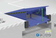
Rampe de incarcare, descarcare - Manual de operare NOVOFERM NovoDock L300
Tip documentatie: Instructiuni montaj, utilizare
Salvează pdf
Full screen
Version: 0.0 Date: 05.05.2009 Page: 1 / 14
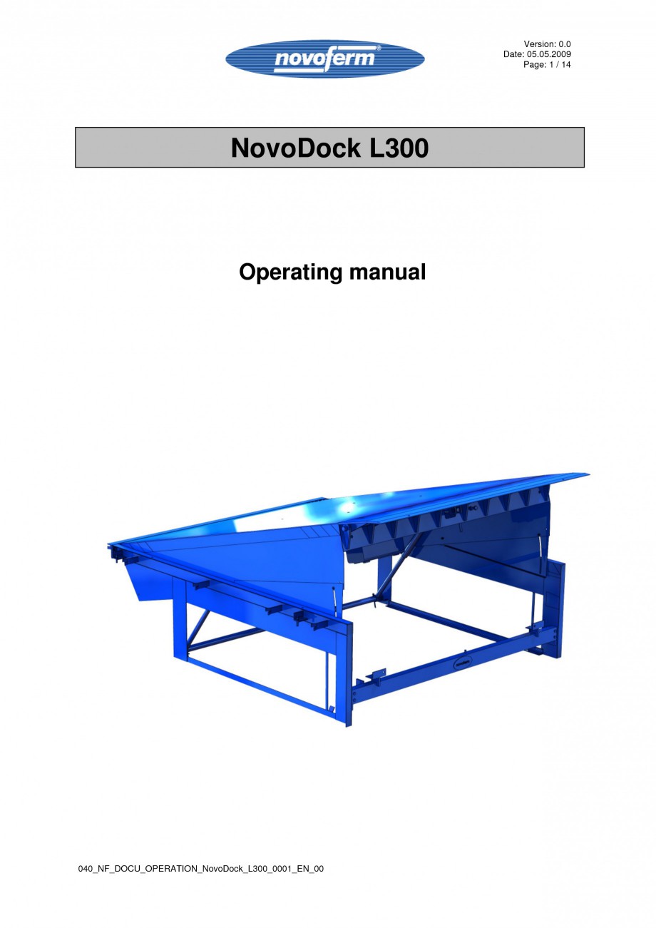
NovoDock L300
Operating manual
040_NF_DOCU_OPERATION_NovoDock_L300_0001_EN_00
Version: 0.0 Date: 05.05.2009 Page: 2 / 14
1 2
GENERAL GUIDELINE AND SAFETY INSTRUCTIONS................................... 3
1.1 COMMENTS ON THE DIAGRAMS ............................................................................................................. 3
GENERAL GUIDELINES .................................................................................... 3
2.1 2.2 2.3 TARGET GROUP ..................................................................................................................................... 3 PURPOSE OF THESE OPERATING INSTRUCTIONS ..................................................................................... 3 USER’S RESPONSIBILITY ....................................................................................................................... 3
3 4 5 6 7 8
SPECIAL INSTRUCTIONS ............................
..................................................... 4 SYMBOLS ON THE DOCK LEVELLER ............................................................. 4 SYMBOLS IN TEXT ............................................................................................ 5 DESCRIPTION OF INTENDED USE .................................................................. 6 OPTIONS DOCK LEVELLER ............................................................................. 7
7.1 FOLD DOWN SEGMENTS ........................................................................................................................ 7
CORRECT USE .................................................................................................. 7
8.1 8.2 MISUSE ................................................................................................................................................. 7 UNSAFE OPERATING PRACTICES ...........................................................................................
................. 8
9 10 11 12
OPERATION ....................................................................................................... 9 COMMISSIONING ........................................................................................... 9 DAILY START UP PROCEDURE ................................................................... 9 OPERATION FUNCTIONS............................................................................ 10
STANDARD OPERATION ....................................................................................................................... 10 INDICATIONS IN DISPLAY .................................................................................................................... 11 ERROR LIST LED DISPLAY .................................................................................................................. 11
12.1 12.2 12.3
13
13.1 13.2
OPTIONAL FUNCTIONS CONTROL UNIT .................................................. 12
DOOR I
NTERLOCK ............................................................................................................................... 12 AUTO BUTTON .................................................................................................................................... 12
14 15
15.1 15.2 15.3
DAILY SHUT DOWN PROCEDURE ............................................................. 12 OPERATION OF THE DOCK LEVELLER .................................................... 12
DOCKING THE VEHICLE ....................................................................................................................... 12 POSITIONING OF THE DOCK LEVELLER ON THE VEHICLE BED .............................................................. 13 LEAVING THE LOADING BAY ............................................................................................................... 13
16 17
TROUBLE SHOOTING USER ...................................................................... 14 REPAIR
......................................................................................................... 14
We reserve the right to alter technical specification.
Version: 0.0 Date: 05.05.2009 Page: 3 / 14
1 General guideline and safety instructions
1.1 Comments on the diagrams
The diagrams in these operating instructions are drawn as an illustration. Some diagrams are simplified for reasons of clarity. The actual specifications depend on the individual dock leveller supplied.
2 General guidelines
2.1
• •
Target group
These operating instructions are intended for users of dock levellers and all persons involved in the installation, operation, preventative maintenance and repair of the equipment Only authorised and fully trained persons who have been informed in detail about the possible risks should operate the dock leveller
2.2
• •
Purpose of these operating instructions
To enable users and engineers to operate and maintain the equipment These operating instructions a
re intended to minimise risk to the life and health of the operator or of a third party
2.3
User’s responsibility
The user of the dock leveller must ensure: • that all persons involved in the installation, maintenance or repair of the dock leveller have read and understood the entire scope of these operating instructions • that any person who is authorised to operate the dock leveller has been thoroughly trained and fully informed about possible risks Note! Always observe the Health and Safety Regulations which apply to your company! Should you have any questions, please contact Novoferm.
We reserve the right to alter technical specification.
Version: 0.0 Date: 05.05.2009 Page: 4 / 14
3 Special instructions
The dock leveller is designed and constructed to operate at maximum safety levels. However, the manufacturers cannot be held responsible for accidents or damage to the dock leveller if the following safety instructions are not observed. • The dock leveller should only
be operated by trained, authorised personnel • The dock leveller must be disconnected and immobilised before installation, resetting, commissioning, maintenance and repair • Safety equipment must not be removed or to be set out of order • Avoid all actions that could adversely affect the operation of the dock leveller • No alterations may be made to the dock leveller without the prior consent of the manufacturer • The dock leveller should only be operated if it is in perfect working order. Any faults should be reported to the person in charge • All the regulations relating to dock levellers, even those not specially mentioned in this manual, should be adhered to • Always observe the accident prevention regulations fucked down by the company • Ensure a firm footing when operating the dock leveller • While loading / unloading the lip has to lie firmly approx. 80 to 130mm and over its whole width on the vehicle bed • The dock leveller should only be operated in an amb
ient temperature of between –20°C and + 40° C • Traffic on the dock leveller must not weigh more than the load capacity of the leveller • The dock leveller must not be used outside the permitted gradient of ± 12.5% (approx. ± 7° ) • Maximum speed on the leveller should be more then 7km/h
4 Symbols on the dock leveller
The following symbols are attached to the dock leveller at dangerous points:
Black and yellow warning stripes indicate a trip hazard! Orange signs at the frame or the platform indicate that the slope is too high!
We reserve the right to alter technical specification.
Version: 0.0 Date: 05.05.2009 Page: 5 / 14
5 Symbols in text
Note: Caution: Danger: tips and recommendations for the operator. risk of damage to supplier. danger to life.
Indications and warnings within the text are illustrated by means of symbols. The symbols have the following meaning: Caution / Danger / General warning!
Danger! High voltage!
Danger! Falling objects!
Danger! Risk of t
ripping!
Note! Lifting equipment to be attached here only!
We reserve the right to alter technical specification.
Version: 0.0 Date: 05.05.2009 Page: 6 / 14
6 Description of intended use
1 12 6 8 2
9
AUT O
10
11
Leveller type NovoDock L300
Lip length 400mm
1 2 3 4
Leveller platform Hinged lip Leveller frame Toe guards
5 6 7 8
Warning stripes Hydraulic unit Lift cylinders Hinged lip cylinder
9 10 11 12
Buffers Tail-lift recess Control unit Cable harness
The dock leveller is designed to bridge the difference in height and distance between the warehouse floor level and the vehicle bed. The leveller essentially consists of a platform the rear end of which is supported by a hinge at dock height, while the front end is provided with a hinged lip. The hinged lip of the NovoDock L300 bridges steplessly the gap between the edge of the dock and the lorry bed, if fully extended. The leveller platform adjusts to sloping lorry beds by distorting laterally while the lip has to lie f
irmly 80 to 130mm wide and over its entire width on the vehicle bed. It also adjusts to the variations in height of the vehicle bed during loading/unloading. In the cross-traffic (parked) position the dock leveller is fully supported in its horizontal position. In this position, the leveller has its full load bearing capacity and traffic can pass over it. The dock leveller is operated electro-hydraulically. The platform is raised and lowered by two hydraulic cylinders and the hinged lip controlled by another hydraulic cylinder. The hydraulic pump/motor and the hydraulic cylinders are located beneath the leveller platform. The electric controls are housed in one box which can be fitted to the wall.
We reserve the right to alter technical specification.
Version: 0.0 Date: 05.05.2009 Page: 7 / 14
7 Options dock leveller
7.1 Fold down segments
The dock leveller with hinged lip can be supplied with fold down segments. On this version the lip is made up of a centre section with a segment
on the left and right side. The side segmentscan be fold down independently of the centr section. This allows the width of the lip to be reduced so that narrower vehicle beds can be accommodated. When the hinged lip returns to the vertical position, the segments are automatically re-engaged. The central section and the segments will move together when the dock leveller is raised the next time, allowing the full width again to be used (see illustration below).
8 Correct use
The purpose of the dock leveller is to bridge the difference in height and distance between the warehouse floor level and vehicle bed. Driving on the dock leveller is only allowed if the lip is securely resting on the vehicle bed or if the dock leveller is in the cross-traffic position and the red control light (see description on page 11) in the control box is not illuminated or there is an indication on the display. The load on the dock leveller should not exceed the load capacity quoted on the specification plat
e. The dock leveller shall not be operated above or below the permitted maximum rise or fall as stated in European safety standards signed on the platform/frame with yellow marks.
8.1
Misuse
Any other use of the dock leveller other than described in “Correct Use” is deemed to be misuse. Misuse refers in particular to: • driving over the dock leveller carrying a load exceeding that stated on the specification plate • driving over the dock leveller with lift trucks which are wider than the nominal width of the dock leveller minus 700mm • operating the leveller whilst under load • transporting persons
We reserve the right to alter technical specification.
Version: 0.0 Date: 05.05.2009 Page: 8 / 14
8.2
•
Unsafe operating practices
Driving on the dock leveller is not safe if the red control light (see description on page 11) in the control box is illuminated or there is an indication on the display (see description on page 10) Operation of the dock leveller after expir
y of the maintenance period is not permitted. The next service date is marked on the specification plate The dock leveller should not be operated if it is malfunctioning or damage has been detected The dock leveller should not be operated if the lip is not resting firmly 80 to 130mm wide and over its whole width on the vehicle bed The dock leveller must not be used if the vehicle to be loaded/ unloaded is not securely parked Driving on the dock leveller with a high speed in combination with a panic braking
• • • • •
Note! Driving over the dock leveller with fork lifts with small wheels and/or high loading frequency can lead to deformings on the upper deck. This has no impact on the function and safety of the dock leveller and is no reason for claiming.
We reserve the right to alter technical specification.
Version: 0.0 Date: 05.05.2009 Page: 9 / 14
9 Operation
This section describes the complete operation of the dock leveller. In order to ensure safe operation of this e
quipment the following safety instructions must be observed. Caution! Make sure that there are no persons in the working area of the dock leveller while the leveller is being positioned or parked. Caution! The dock leveller is to be operated by trained persons (minimum age 18 years) only. During operation, the movement of the dock leveller must be closely watched. Caution! All persons operate a dock leveller must be familiarize with the function. The user has to ensure that all persons concerned have understood the instructions. The operator must have read the operating manual attentively. Caution! In case of emergency, turn the yellow-red mains isolator to “0”. Any movement of the dock leveller will then be interrupted. Any movement of the dock leveller is immediately interrupted if: • the mains isolator is switched off or • the mains supply is interrupted After any interruption to the dock leveller power supply, the push button “Lift” must be pressed after restoration of
... ascunde
Alte documentatii ale aceleasi game Vezi toate
Fisa tehnica
20 p | GE
NovoDock L300 NovoDock H1300 NovoDock H1500 NovoDock L100 NovoDock L150 NovoDock L350i NovoDock P1300i NovoDock P1500i
Instructiuni montaj, utilizare
18 p | EN - GE
NovoDock L300