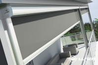
Rulou din material textil (Box) LLAZA Maxi Screen
MAXISCREEN BOX
Technical Manual
MAXISCREEN BOX
MAXISCREEN BOX
Page 2 - Copyright Llaza World, S.A.
MAXISCREEN BOX
Contents
Descriptive specifications
5-7
Cutting, selection, and classification tables
8-9
Annotated cross-sectional diagrams
Assembly instructions
10
11-18
Examples of installations
19
Page 3 - Copyright Llaza World, S.A.
MAXISCREEN BOX
Page 4 - Copyright Llaza World, S.A.
MAXISCREEN BOX
Page 5 - Copyright Llaza World, S.A.
MAXISCREEN BOX
Descriptive specifications
1 – GENERAL CHARACTERISTICS
Awnings that use the MAXISCREEN BOX vertical system are the ideal vertical awnings for installations that
require the light in large spaces to be managed and controlled but want minimal impact on the structure of
glass walls, windows and façades.
The attractive support structure – which is both contemporary and minimalist – will increase your installation
possibilities while also greatly reducing the installation time needed. Our BOX system provides an
added
value to the advantages of the system: the overall protection of the fabric.
2 – DESCRIPTION OF THE SYSTEM
The advanced technology of the MAXISCREEN BOX system brings a series of advantages to the
installation which guarantee maximum performance from the awning:
■ Improved durability of the fabric thanks to the BOX system
■ Enhanced strength
■ Easy installation: As the bracket structure includes end guides and a gearbox or motor, assembling the
section that holds the fabric is greatly simplified as it is inside the profile of the BOX.
As with any sun protection system, this product also seeks maximum suitability for each installation in terms
of two intrinsic necessities:
■ Dimensions
■ Demands (sun, wind, rain)
To address these factors, the materials chosen in the manufacture of this product are of vital importance.
3 – DESCRIPTION OF THE PARTS THAT MAKE UP THE AWNING
A multifunctional, adaptable bracket structure that can be installed anywhere: frontal, ceiling
or between walls.
The roller tube, inside which the fabric is rolled up and from which it extends, is positioned in
such a way that the overall installation of the BOX is very easy and minimal time is needed for this
process.
Despite its small size, it can hold rolls of fabric that have up to a 5-metre drop.
A gearbox guide system and aluminium end guides adaptable for vertical positions to
ensure support while being lowered and raised.
A bolt-type anchor element for the tension chosen (cord or rod) that can be positioned to the
desired angle.
Page 6 - Copyright Llaza World, S.A.
MAXISCREEN BOX
Descriptive specifications
Hidden cord or rod restrictor bolt inside the tensor. This system enables the
restrictor bolt to rotate inside the tensor while the blind is being pulled taut,
preventing the cord from twisting and leading to a slackening of the blind.
The head of the bolt is hexagonal to make it easy to tighten with a tube
spanner when it is in any position.
The acrylic or high-
tech fabric offers superior sun protection and extends and retracts by rolling on a steel
tube.
The rotational motion applied to the rolling tube when extending or retracting the fabric takes place using a
gearbox with a 1:10 ratio, operated with a crank or by means of an electric motor located inside one end of
the rolling tube.
At the other end, a polyamide bearing ensures technically calculated support so the system operates
smoothly and perfectly every time.
The fabric extends smoothly, helped by the counterweights in the load bar.
4 – FINAL CONSIDERATIONS
■ Thanks to our manufacturing processes and their corresponding management controls we have been
awarded the ISO-9001:2008 certification for design and manufacturing.
■ Our compliance with the requirements of European standard EN 13561 allows us to issue a Statement
of Conformity for the CE marking.
■ The application of the conditions required by EAA/Qualicoat standards allow us to offer a 3-year
guarantee on lacquer fi
nishes.
Page 7 - Copyright Llaza World, S.A.
MAXISCREEN BOX
Descriptive specifications
5 – COMPONENT SPECIFICATIONS
DIMENSIONS
Geometry
Section (2mm)
Mt (4cm)
Front 3656 profile
-
431.97
Ixx= 17.47 Iyy= 4.36
3904 BOX profile
-
745
Ixx= 126.34 Iyy= 144.85
TECHNICAL CHARACTERISTICS
Structure
Components
Manufacturing
process
Cast
Material used
A*
B*
C*
D*
Aluminium
170
80
5
55
Profile
Steel
296
195
28
89
Extrusion
AISI-304
Roller tube
8mm guide rod
3mm cord
19 x 0.6 braid
AISI-316
Injection
Polyamide 6
Mechanised
AISI-303
Mechanised
AISI-303
Side guides
Restrictor bolts
Hexagonal tensor
DESCRIPTION
A*
Resistance to traction
Rm (Mpa)
B*
Stretch limit
Rp 0.2 (Mpa)
C*
Elongation
A50 mm (%)
D*
Brinell hardness
HBS
MAXIMUM WIDTHS AND DROPS, DEPENDING ON THE Ø OF THE ROLLER TUBE AND TYPE OF FABRIC
Ø 65 mm
With screen fabric (0.6 mm thick and horizontally soldered)
With acrylic fabric (0.5 mm thick and vertically stitched)
WIDTH
(m)
3.50
3.50
DROP (m)
7.00
5.00
Ø 70 mm
With screen fabric (0.6 mm thick and horizontally soldered)
With acrylic fabric (0.5 mm thick and vertically stitched)
WIDTH
(m)
4.00
4.00
DROP (m)
6.50
4.00
Ø 80 mm
With screen fabric (0.6 mm thick and horizontally soldered)
With acrylic fabric (0.5 mm thick and vertically stitched)
WIDTH
(m)
5.00
5.00
DROP (m)
5.00
3.00
Page 8 - Copyright Llaza World, S.A.
MAXISCREEN BOX
5 – CUTTING, SELECTION, AND CLASSIFICATION TABLES
EN 13561 STANDARD – WIND CLASSIFICATION TABLE
CLASSIFICATION
RANGE (Km/h)
BEAUFORT
CLASSIFICATION 0
0 to 19
1-3 Beaufort
Leaves and small twigs constantly moving.
CLASSIFICATION 1
20 to 28
4 Beaufort
Dust and loose paper raised. Small branches begin to move.
CLASSIFICATION 2
29 to 38
5 Beaufort
Branches of a moderate size move. Small trees in leaf begin to sway.
CLASSIFICATION 3
39 to 49
6 Beaufort
Large branches in motion. Umbrella use becomes difficult.
MOTOR SELECTION TABLE
WIDTH (m)
1.00
1.50
2.00
2.50
3.00
3.50
4.00
4.50
5.00
1.50
ROLLER TUBE Ø 70
2.00
2.50
6 Nm
3.00
3.50
4.00
6 Nm
5.00
10 Nm
6 Nm
10 Nm
1.50
ROLLER TUBE Ø 80
DROP (m)
4.50
6 Nm
2.00
2.50
10 Nm
6 Nm
3.00
3.50
10 Nm
6 Nm
4.00
10 Nm
4.50
6 Nm
5.00
10 Nm
ASSEMBLY ALLOWANCES vertical MAXISCREEN-BOX
OUTER GEARBOX
ROLLER
Ø 70 OR Ø 80 ROLLER TUBE TUBE
--R
CANVAS
--FABRIC
FRONT PROFILE
--CASSETTE PROFILE
TEXPRO CASSETTE PROFILE
FRONT DROP BAR PROFILE
INNE
GEARBOX
GEARBOX
L-131 L-125
L-141
L-110
L-130
SOMFY MOTOR
SOMFY MOTOR
L-97
L-115
L-135
L-110
L-130
GUIDE CORD Ø 3 mm.
STAINLESS GUIDE ROD Ø 3 mm
L= total
width measurement H= total height
Page 9 - Copyright Llaza World, S.A.
MAXISCREEN BOX
6 – CROSS SECTIONS
Page 10 - Copyright Llaza World,
S.A.
MAXISCREEN BOX
7 – ASSEMBLY INSTRUCTIONS
1 – Mounting the brackets
FRONTAL
Page 10 - Copyright Llaza World, S.A.
MAXISCREEN BOX
2 – Attaching the fabric to the roller tube
Roll the fabric around the tube i
n the direction indicated in the drawing
so that the when it drops vertically it will be next to the cord or rod guide.
Next, place the end bearing on the opposite side of the operating
system (gearbox or motorised).
NB: In this specific case, the very end would be on the left.
3 – Fitting the side guides
THE INSIDE OF THE GEARBOX
B
Use DIN 7991 (A) screws (included in reference 11 002 040
000) to attach the gearbox to the bracket guide, then attach
the side cover of the box system and its corresponding nuts
(B).
It is important not to forget to attach the end bearing (C)
between the gearbox end bearing of the axle and the side of
the box system.
A
C
A
The structure will be thus be securely attached and the heads of the screws (A)
will be flush to the surface thanks to the countersink in the gearbox guide.
It is advisable to prepare these pieces before inserting the profile box over the
roller tube and the fabric.
E
D
MOTOR
If you have chosen an electric motorised system, a
ttach the
bracket for the motor (D) to the bracket guide, placing the
side cover of the box system between them. Use DIN 7991
screws (E) for this, found in REF. 11002035050, to then clip
the motor head to the above-mentioned bracket using the
attachment clip (F).
F
Page11 - Copyright Llaza World, S.A.
MAXISCREEN BOX
On the opposite side, attach piece (G) to the side of the box
system where the end of the bearing will be inserted. Attach
this piece with the corresponding screws (H).
H
G
4 – Installing the cassette and the side end cover
Put the end of the roller tube into the cassette profile and then screw
both ends of the box profile to the side covers (gearbox and end) with
the appropriate screws (I).
i
5 – Installing the load bar and the guide system
K
J
Insert the load bar (J) into the bottom of the fabric, in the
position shown in the drawing. This allows a solid or hollow
20-mm diameter counterweight to be inserted in the lower
part of the bar, depending on the re
quirements of the
installation and the size of the product.
The fabric is attached to the profile with the same raw plug
and screw that will secure it to the side cover (K).
These side covers allow a rod or cord guide to be inserted
into them or even a flat cap in the case of a free-drop or
guide-free awning.
Page12 - Copyright Llaza World, S.A.
MAXISCREEN BOX
Assembly instructions
6 – Attaching the tensor system
L
M
N
O
P
Page13 - Copyright Llaza World, S.A.
MAXISCREEN BOX
7 – EXAMPLES OF INSTALLATIONS
Page14 - Copyright Llaza World, S.A.
MAXISCREEN BOX
NB: LLAZA WORLD, S.A. owns the copyrights to the photographs, illustrations and text of this publication and
these may not be used, copied, or reproduced in any form, nor by any means, whether chemical, thermal,
magnetic, digital, or analogue, without prior permission from LLAZA WORLD, S.A.. The company reserves the
right to take legal action in the event of unauthorised usage.
Page15 - Copyright Llaza World, S.A.
MAXISCREEN BOX
LLAZA WORLD, S.A.
- Tramuntana, 1 - Polígono Ind. Roques Roges (C.D. 1) - 43460 - ALCOVER
Tel. +34 977 990 600 - Fax +34 977 990 610
info@llaza.com - export@llaza.com www.llaza.com
Alte documentatii ale aceleasi game Vezi toate
Fisa tehnica
28 p | EN
Bip 500
Fisa tehnica
26 p | EN
Bip 300