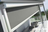
Rulou din material textil perforat LLAZA Bip 300
BIP - SCREEN 300
Technical Manual
BIP - SCREEN 300
Page1 - Copyright Llaza World, S.A.
BIP - SCREEN 300
Page 2 - Copyright Llaza World, S.A.
BIP - SCREEN 300
Contents
EXPLODED VIEW OF PRODUCT AND REFERENCES
1. CUTTING AND SELECTION TABLES
3
4
1.1. BIP - SCREEN 300 assembly allowances
4
1.2. Fabric assembly allowances
5
1.3. Choosing the fabric
6
1.4. Description of the roller tube
6
1.5. Description of the counterweights
7
1.6 Choosing the motor
7
2. CROSS SECTIONS
8
3. ASSEMBLY INSTRUCTIONS
9
3.1. Assembly of the cassette
9
3.2. Preparing the roller tube
12
3.3. Preparing the fabric
13
3.4. Load bar
15
3.5. Guide profiles
16
4. ASSEMBLY INSTRUCTIONS
17
4.1. Installation with wall/ceiling brackets
18
4.2. Installation without wall/ceiling brackets
19
5. CHANGING THE FABRIC
22
Page 3 - Copyright Llaza World, S.A.
BIP - SCREEN 300
1. CUTTING AND SELECTION TABLES
1.1. BIP SCREEN 300 ASSEMBLY ALLOWANCES
Sizes in mm
MOTOR Ø40
CASSETTE HOUS
ING
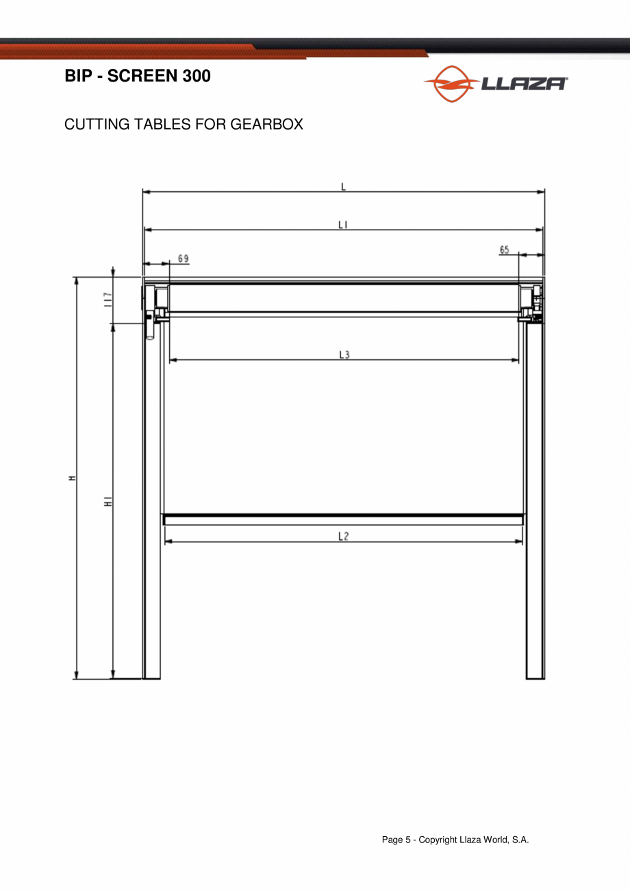
L - 8 mm
FRONT PROFILE
GEARBOX
L - 8 mm
ROLLER TUBE
L - 114 mm
L - 134 mm
LOAD BAR
L - 106 mm
PROTECTIVE HEM ROD PROFILE
L - 8 mm
20 x 5 COUNTERWEIGHT
L - 180 mm
BASE GUIDE PROFILE
H - 120 mm
BASE GUIDE COVER
H - 120 mm
L= total length measurement H= total height measurement
20 mm side slots (Add fabric weights to the side hems,
we suggest 20 mm per hem)
The hem rods for the upper and lower slots are the same. (Add the fabric weights
to the H of the roller tube, we suggest +50 mm)
Minimum width 1,200 mm (Please enquire for smaller measurements)
Page 4 - Copyright Llaza World, S.A.
BIP - SCREEN 300
CUTTING TABLES FOR GEARBOX
Page 5 - Copyright Llaza World, S.A.
BIP - SCREEN 300
CUTTING TABLES FOR MOTOR
Page 6 - Copyright Llaza World, S.A.
BIP - SCREEN 300
1.2. SCREEN - BIP 300 FABRIC ASSEMBLY ALLOWANCES FOR ATTACHING
IT TO THE UPPER DROP BAR
GEARBOX MOTOR 40
Sizes in mm
FABRIC WIDTH
UPPER SLOT
L - 62 mm
L - 134 mm
L - 114 mm
LOWER SLOT
L - 106 mm
TOTA
L HEIGHT
H + 50 mm
L= total length measurement H= total height measurement.
20 mm side slots. (Add the fabric weights to the side hems)
The hem rods for the upper and lower slots are the same. (Add the fabric weights
to the H of the roller tube)
Minimum width 1,200 mm (Please enquire for smaller measurements)
Drop height
Page 7 - Copyright Llaza World, S.A.
BIP - SCREEN 300
1.3. CHOOSING THE FABRIC
WIDTH (m)
1
1.5
2
2.5
3
DROP (m)
1.5
4000P/7000P
2
2.5
3
1.4. ROLLER TUBE (mm)
WIDTH (m)
1
1.5
2
2.5
3
1.5
DROP (m)
2
Ø65
2.5
3
1.5.
A
DESCRIPTION OF THE
COUNTERWEIGHTS
20x5
Weight
0.79 kg/m
Page 8 - Copyright Llaza World, S.A.
BIP - SCREEN 300
1.5. DESCRIPTION OF THE COUNTERWEIGHTS
WIDTH (m)
* MINIMUM WIDTH
1.2
1.5
2
2.5
3
DROP (m)
1.5
2
(A)
2.5
3
Note: Recommended counterweights. These figures may vary depending on the characteristics of the installation.
1.6. CHOOSING THE MOTOR
WIDTH (m)
* MINIMUM WIDTH
1.2
1.5
2
2.5
3
DROP (m)
1.5
2
9 N
m
13 Nm
2.5
3
13 Nm
Note: Choose the motor according on the counterweights described in the above table. Modifications to the configuration of the
counterweights may result in a motor that is different from that in the selection table.
For these systems, the motors must have two limit switches: a no-pressure BOX type upper one, and a lower one.
Page 9 - Copyright Llaza World, S.A.
BIP - SCREEN 300
2. CROSS SECTIONS (in mm)
ROLLER TUBE SYSTEM
GUIDE PROFILE
DROP BAR PROFILE
Page 10 - Copyright Llaza World, S.A.
BIP - SCREEN 300
3. ASSEMBLY INSTRUCTIONS
3.1 . Assembling the cassette
B
A
D
E
C
F
MOTOR
Page 11 - Copyright Llaza World, S.A.
BIP - SCREEN 300
GEARBOX
Attach the gearbox directly to the CASSETTE COVER (D) using M 6 x 20 DIN 7991 screws. The bolts are housed in the
gearbox itself.
The gearbox can be assembled in two ways: gearbox with front or rear position.
GEARBOX WITH FRONT POSITION
These diagrams show the configuration of the gearbox at the front.
Note: Th
is configuration requires an opening in the CASSETTE COVER
PROFILE of the size shown in the diagram on the right.
GEARBOX WITH REAR POSITION
The diagram below shows the configuration for the gearbox at the back.
NOTE: This configuration requires an opening in the
CASSETTE PROFILE of the size shown in the diagram on the right.
Page 12 - Copyright Llaza World, S.A.
BIP - SCREEN 300
G
H
D
There are various possible configurations depending on the cassette profile used.
SOFT LINE MODEL
BIP SCREEN 300 CASSETTE PROFILE to assemble
directly into the PROFILE. BIP SCREEN 300
CASSETTE COVER clipped straight onto the front
attachment.
STRAIGHT MODEL
BIP SCREEN 300 STRAIGHT CASSETTE PROFILE to
assemble directly into the PROFILE. BIP SCREEN 300
STRAIGHT CASSETTE COVER clipped straight onto
the front attachment.
Page 13 - Copyright Llaza World, S.A.
BIP - SCREEN 300
3.2. Preparing the roller tube
I
J
I
MOTOR
W
Insert into one end the Ø40 ADAPTER (I) to
fit the roller tube. Next,
insert the Ø40 END
BEARING (J).
THE BEARING ADAPTER must be secured
to the roller tube.
Insert the other Ø40 ADAPTER (I) and the
Ø40 DRIVE WHEEL (K) to the MOTOR.
Attach the MOTOR PLATE (L) to the motor
head with two 4.2 x 13 DIN 7982 screws, as
shown in the diagram.
K
Place the assembled parts into the roller tube.
* The adapters (I) should be secured well to
the roller profile, both on the end side as well
as the side with the motor/gearbox.
I
J
GEARBOX
Insert the ADAPTER (I) to fit the diameter
of both ends of the roller tube.
Both adapters should be well secured to
the roller tube.
I
Insert the BEARING END (J) into the side
with the automatic bracket, and the
GEARBOX ADAPTER (M) into the gearbox
attachment.
M
Page 14 - Copyright Llaza World, S.A.
BIP - SCREEN 300
C
E
65
C
51
55
Page 15 - Copyright Llaza World, S.A.
BIP - SCREEN 300
3.3. Preparing the fabric
N
Insert the HEM ROD TUBE P-650 (N) into the upper hem slot of the
fabric. Insert the Ø5.8mm HEM ROD (
O) into the lower hem slot.
P
Procedure for introducing the BALL CHAIN (P) into the side hem
slots:
Hold the BALL CHAIN (P) at the end of a section of the HEM ROD
(N), making sure that it extends a little above the side slots of the
fabric. Insert the end of the HEM ROD, free of the BALL CHAIN,
and slide it until it emerges from the other end of the rod with the
BALL CHAIN.
Secure by sewing the BALL CHAIN to the upper end and then cut
off the excess BALL CHAIN, leaving a little extra hanging from the
fabric. There should be three balls hanging out of the end of the
fabric.
Plastic guide
Staples
Staples
Plastic guide
Plastic guide
Insert the plastic fabric guide into the side hem so that it is flush
with the lower part of the hem. Secure it with two staples as
shown in the diagram.
3.4. Load bar
O
The internal measurements of the load profile
allow the configurations of the counterweights
to be adjusted to meet the specific needs of
each installation.
The system allows the fol
lowing to be used:
From 1 to 3 metres (to be used inside
the load bar) 2 20 X 5 mm gussets (O)
weighing 0.79 kg/m
Page 16 - Copyright Llaza World, S.A.
BIP - SCREEN 300
3.4. Load bar
Q
(Q)
3.5 . Guide profiles
R
S
Page 17 - Copyright Llaza World, S.A.
BIP - SCREEN 300
3.5. Guide profiles
Attach the FUNNEL (T) to the upper section of the GUIDE PROFILE
BASE (R) using a 4.2 x 25 DIN 7982 screw.
T
If the cover is simply decorative, attach the LOWER GUIDE-45
COVER (W) to the lower section of the GUIDE PROFILE BASE using
a 4.2 x 25 DIN 7982 screw.
If you want to attach the GUIDE PROFILE BASE to the floor, use the
GUIDE-45 FLOOR COVER (X).
R
In the case of the PROFILE BASE COVER, an additional piece (V)
must be added to the upper part of the funnel (U) and secured with a
4.2 x 45 screw as shown in the diagram. This will serve as a limit to
the opening of the load profile.
V
U
In addition, the funnels (T) and (U) must be secured with a 4.2 x 16
screw after they have been
clipped to the GUIDE PROFILES.
Screw in the end cover (W) to the lower section of the
PROFILE BASE COVER (R) with a 7982 DIN screw when the
base has been attached in a facing position or between two
walls.
S
W
X
The end cover (X) must be attached to the lower section of the
PROFILE BASE COVER (S) when it is attached to the floor
and not attached in a facing position or between two walls.
Page 18 - Copyright Llaza World, S.A.
BIP - SCREEN 300
4. ASSEMBLY INSTRUCTIONS
4.1. Installation with wall brackets
4.1 . Installation with ceiling brackets
Page 19 - Copyright Llaza World, S.A.
BIP - SCREEN 300
4.2 . Installation without wall/ceiling brackets
B
X
Page 20 - Copyright Llaza World, S.A.
BIP - SCREEN 300
Page 21 - Copyright Llaza World, S.A.
BIP - SCREEN 300
Page 22 - Copyright Llaza World, S.A.
BIP - SCREEN 300
DETAIL OF HOW THE GUIDE
SHOULD BE CLIPPED
FABRIC
FABRIC
CLICK!
CLICK!
Page 23 - Copyright Llaza World, S.A.
BIP - SCREEN 300
5. CHANGING THE FABRI
C
Page 24 - Copyright Llaza World, S.A.
BIP - SCREEN 300
(1)
(2)
(3)
Do not open the automatic end bracket with any other
metal tool other than a flat screwdriver. The correct way to
open it is by pushing the head of the bracket with the end
of a screwdriver placed in the groove of the housing as
indicated.
It can also be done by simply pushing the head of the
bracket with your fingers.
Page 25 - Copyright Llaza World, S.A.
BIP - SCREEN 300
LLAZA WORLD, S.A.
- Tramuntana, 1 - Polígono Ind. Roques Roges (P.O. Box 11) - 43460 - ALCOVER
Tel. +34 977 990 600 - Fax +34 977 990 610
info@llaza.com - export@llaza.com www.llaza.com
PAGE.2 - Copyright Llaza World, S.A.
Alte documentatii ale aceleasi game Vezi toate
Fisa tehnica
28 p | EN
Bip 500
Catalog, brosura
706 p | EN
Bip 300 Bip 500 Maxi Screen Aluminiu Lemn